Quick Tips: What is control voltage and how does it work?
Get to know the CV/Gate system, the pre-MIDI method that synths, sequencers and music tech gear uses to communicate

Before the advent of MIDI, there was only one realistic method for interfacing all of your pieces of equipment with each other. Control voltage, more commonly known as CV and more accurately known as CV/Gate, is a system that uses very simple analogue electrical signals to trigger equipment.
The CV/Gate system has two parts: the control voltage itself and a separate gate (aka trigger) signal. Both trigger a note, but the CV element can be thought of as the part that determines the pitch, while the gate determines the note on/off timing. CV control needs two separate signals, often transmitted over two cables for flexibility.
Given that it emerged in the years before standardisation of equipment control protocols, it’s unsurprising that there are multiple variations. Most notably, not all synths expect control voltages in the same range.
Vintage Korg and Yamaha synths tend to use the Hz/V (Hertz per volt) system, where the frequency of the oscillator rises and falls in proportion to the voltage of the CV signal, while most other manufacturers favoured the V/Oct (volts per octave) system, in which the voltage rises by one volt per octave. This latter setup is now the standard for Eurorack and modern semi-modular gear.

Likewise, different synths expect subtly different gate signals. Some use a positive trigger, where the presence of a voltage indicates that a key is being pressed; others use a short-circuit trigger system where the gate signal shorts out and drops to zero volts when the key is pressed (also sometimes known as a negative trigger or S-Trig). The voltage of the gate signal also varies between manufacturers. The good news is that modern gear tends to let users adapt.
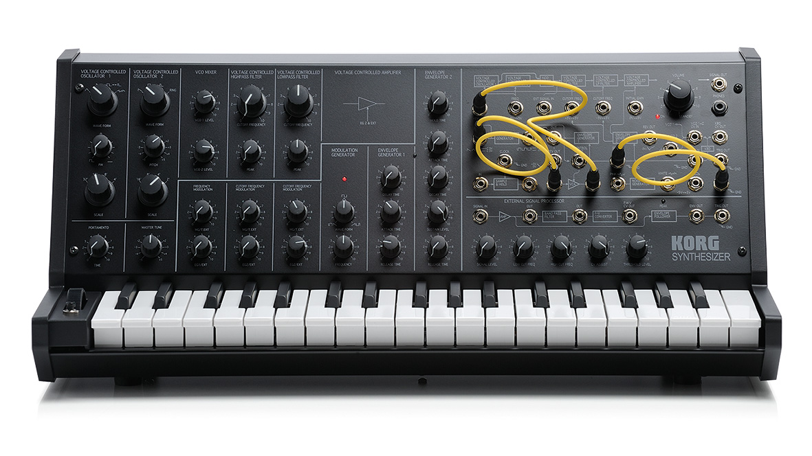
CV isn’t just for sending note information. When you patch, say, an envelope generator’s signal to a VCA on a semi-modular synth like the Korg MS20 or ARP 2600, you’re routing a control voltage from one section to another. If you route a square wave LFO to the trigger input of a step sequencer, you’re effectively using it as a gate signal.
Although most signals are considered either to be CV or audio signals, there’s no reason you can’t mix the two up. For instance, sending an audio signal to a CV input effectively allows it to work as a control voltage. An LFO signal with its rate increased into the audible range can be used like any oscillator.
Want all the hottest music and gear news, reviews, deals, features and more, direct to your inbox? Sign up here.
I'm the Managing Editor of Music Technology at MusicRadar and former Editor-in-Chief of Future Music, Computer Music and Electronic Musician. I've been messing around with music tech in various forms for over two decades. I've also spent the last 10 years forgetting how to play guitar. Find me in the chillout room at raves complaining that it's past my bedtime.