Guitar DIY: how to wire a Strat for two humbuckers
You can slap nearly any pickup into a Strat… space permitting
Want all the hottest music and gear news, reviews, deals, features and more, direct to your inbox? Sign up here.
You are now subscribed
Your newsletter sign-up was successful
Last time we looked at a 7-way circuit for a Strat, for this how-to guide we’ll be wiring up a parts-o-caster Strat project in a non-traditional way and although it’s a Strat we’ll be using two pickups and three pots with a tone control for each pickup.
Normally reserved for Firebirds and Les Pauls we’ve got some Mini Humbuckers, provided there’s room under the pickguard you can slap nearly any pickup into a Strat!
- Start a new project with the best DIY guitar kits
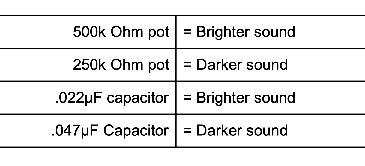
As we’re going off-menu with this project let’s think about the part we need. We're choosing 500K Ohm pots. Why? Nearly any value of potentiometer will work but different values will affect the high frequencies due to attenuation. A higher resistance pot will bleed less high frequency to ground which is why generally darker sounding humbuckers are paired with pots of a higher value to avoid draining any more treble away.
How to set up your guitar: a DIY guide to intonation, truss rod, bridge and fretboard maintenance
Conversely, a real twanger like a Tele single coil pikcup will likely be paired with a 250k ohm pot to tame the treble. Go all the way for as bright as you can with a 1 Meg Ohm potentiometer, as used in Jaguars for all the bite you can stomach!
We’ve chosen a .022µF to give a decent range to the tone controls. On a tone pot circuit you will attenuate (bleed) treble through the potentiometer then through the capacitor, similarly on a volume pot you will only attenuate through the pot. The value of the capacitor and potentiometer will influence the sound even when turned up to 10.
You’re free to experiment with different values of course but here’s a quick lowdown:
Tools you will need
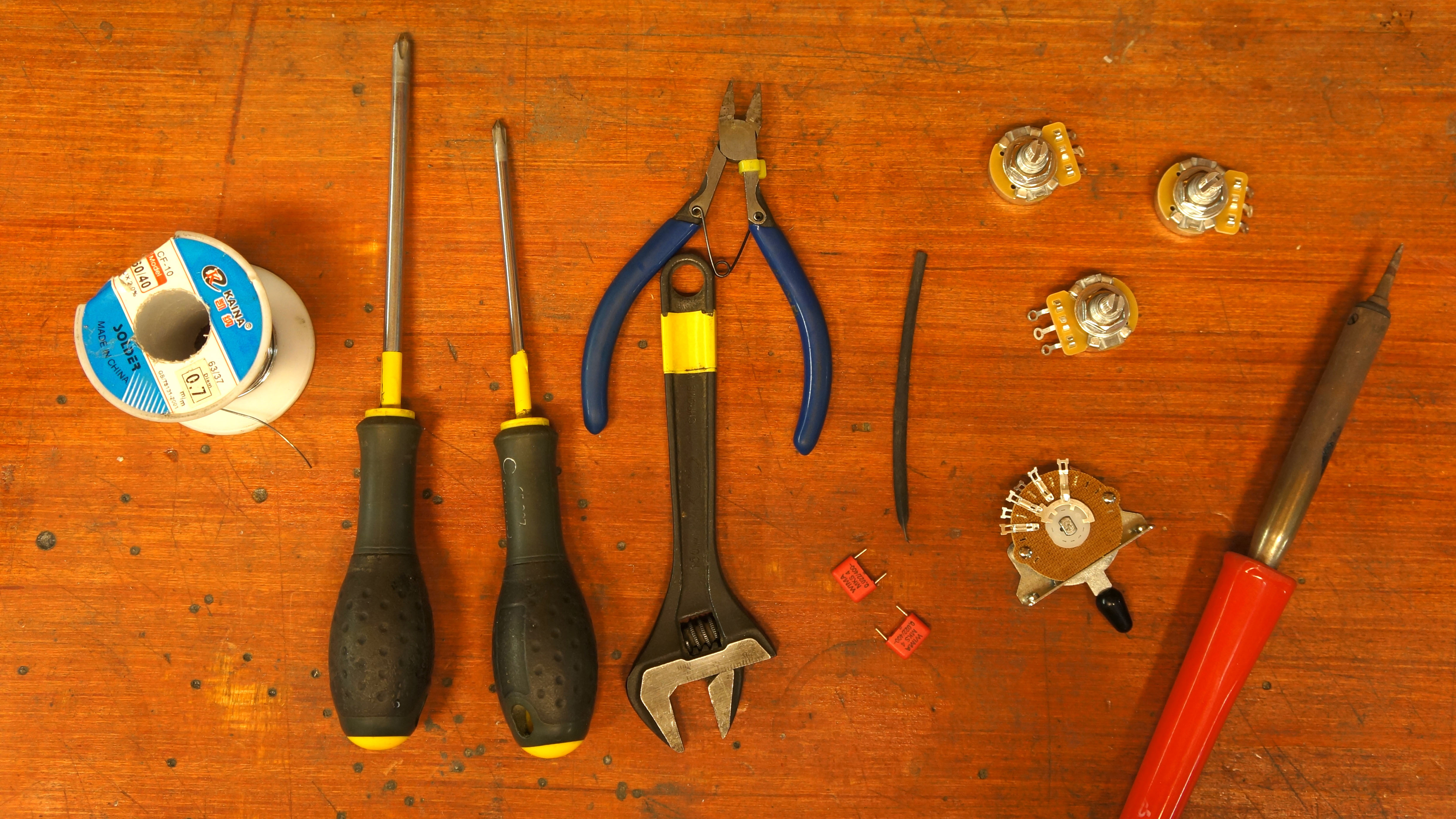
- A500k Ohm Pots x3
- 3 Way pickup switch
- .022µF Tone capacitors x2
- Cloth wire
- Shrink Tubing
- Pickups of choice
- 40 Watt soldering iron
- PH2 screwdriver
- PH1 screwdriver
- 60/40 Solder
- Wire Cutters
- Adjustable spanner
- Optional: Crocodile clip tester tool
Wiring
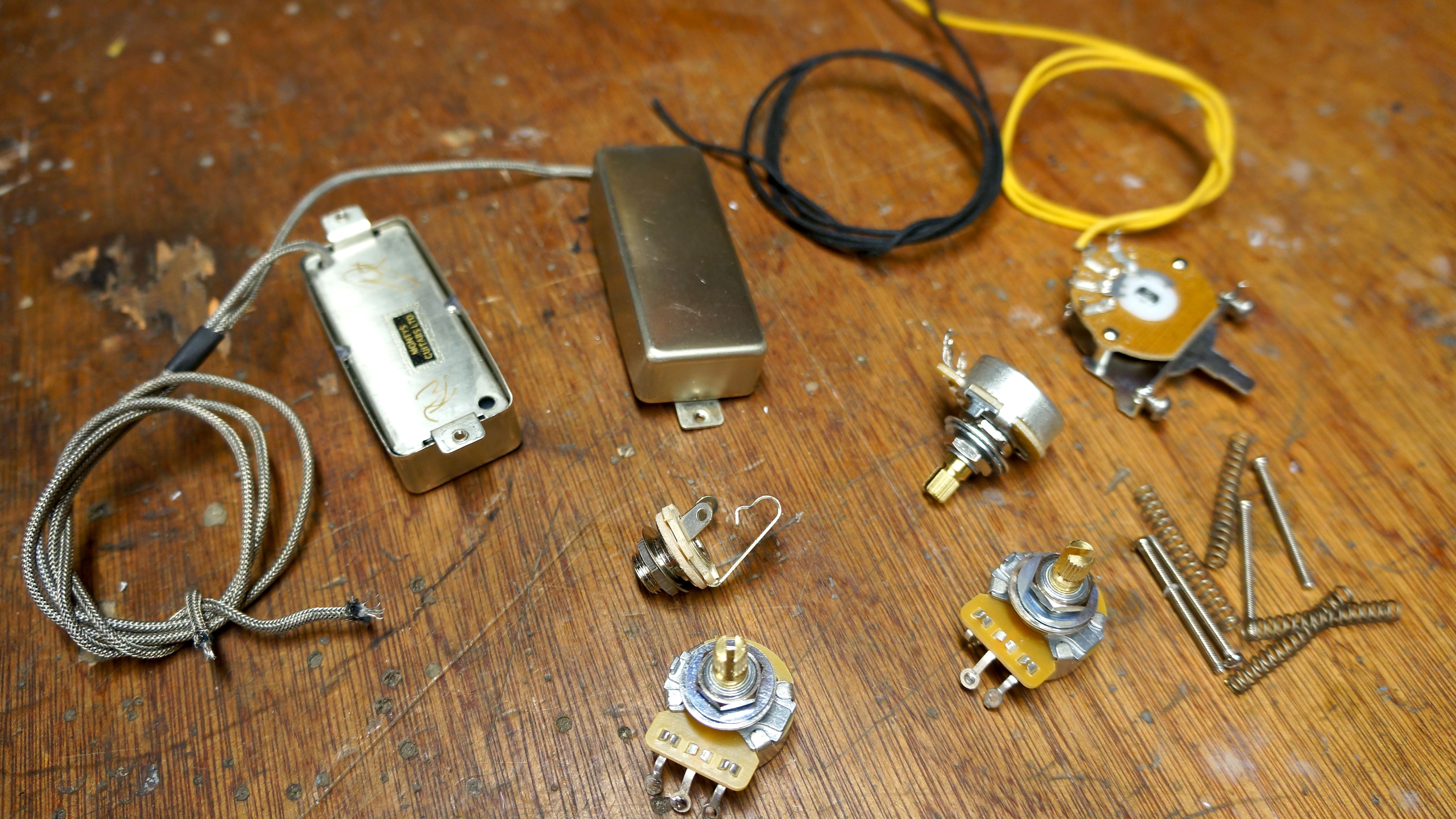
Here’s the parts we’ve selected: A500K CTS pots, and Oak Grigsby three-way pickup switch, Switchcraft jack socket plus some .022µF Polypropylene capacitors. The circuit will be completed using all cloth covered wire, you know... so it looks cool!
Want all the hottest music and gear news, reviews, deals, features and more, direct to your inbox? Sign up here.
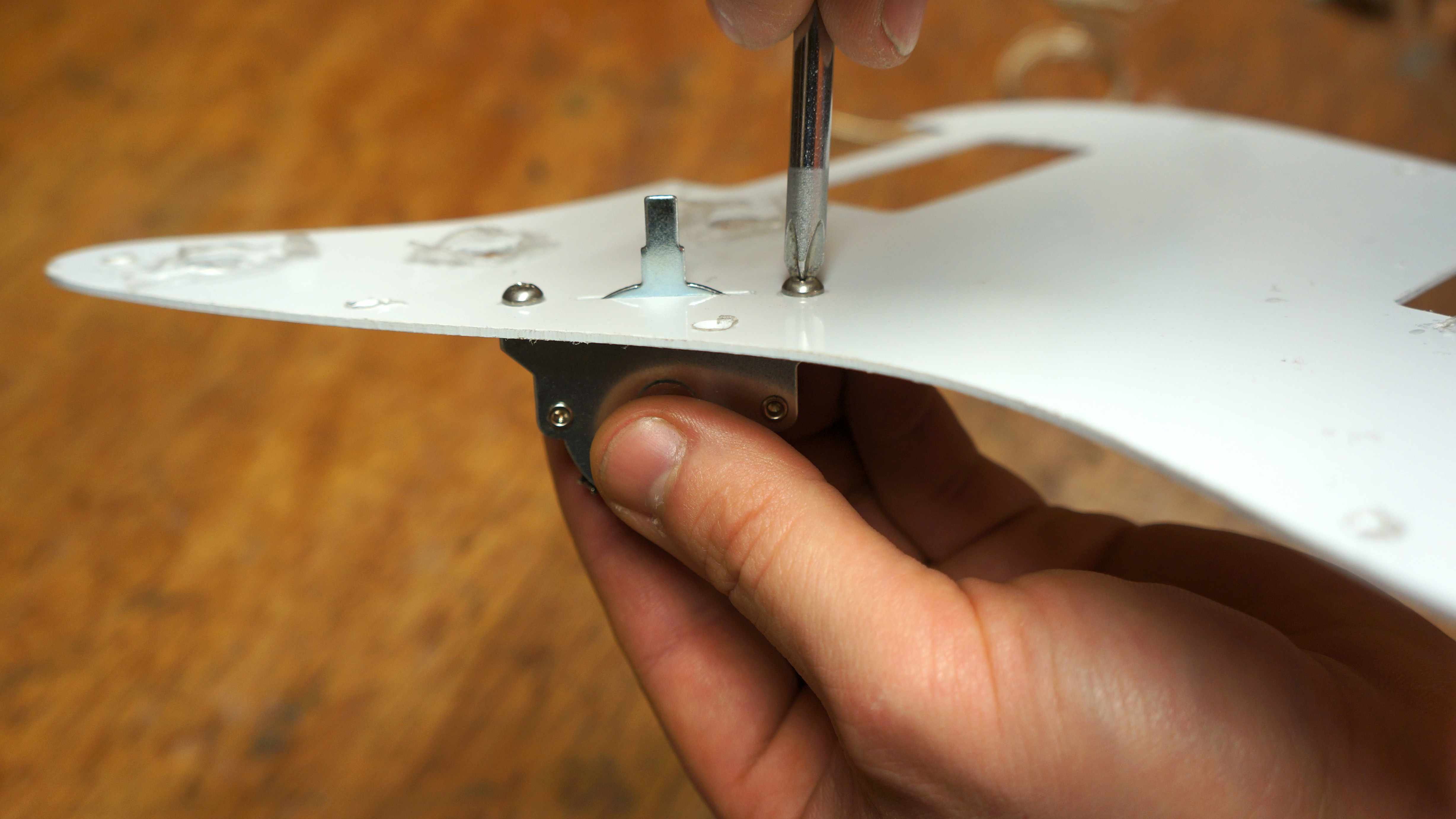
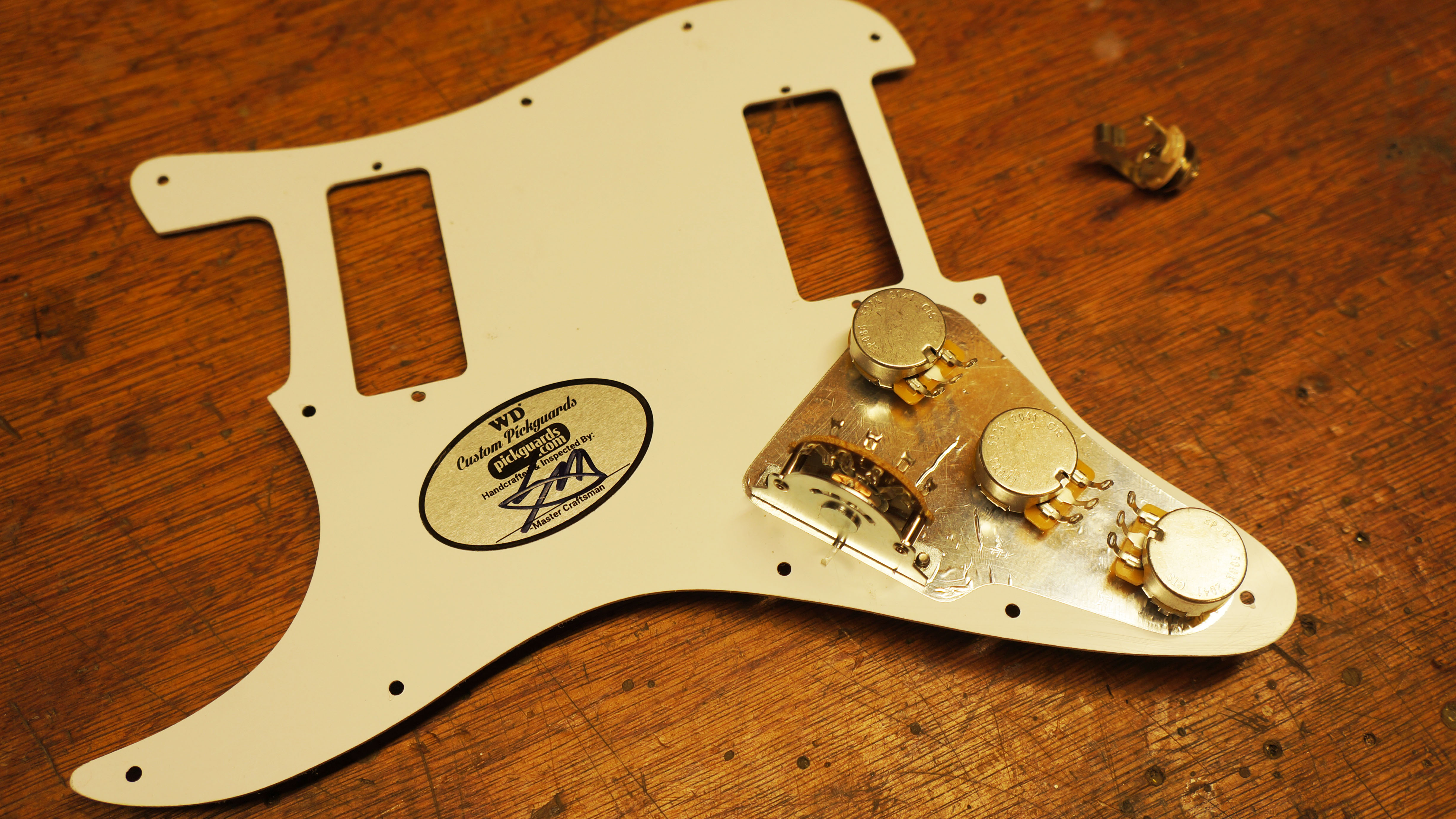
Let’s start fitting all the parts into the pickguard, load the switch in so that the terminals face towards the pots.
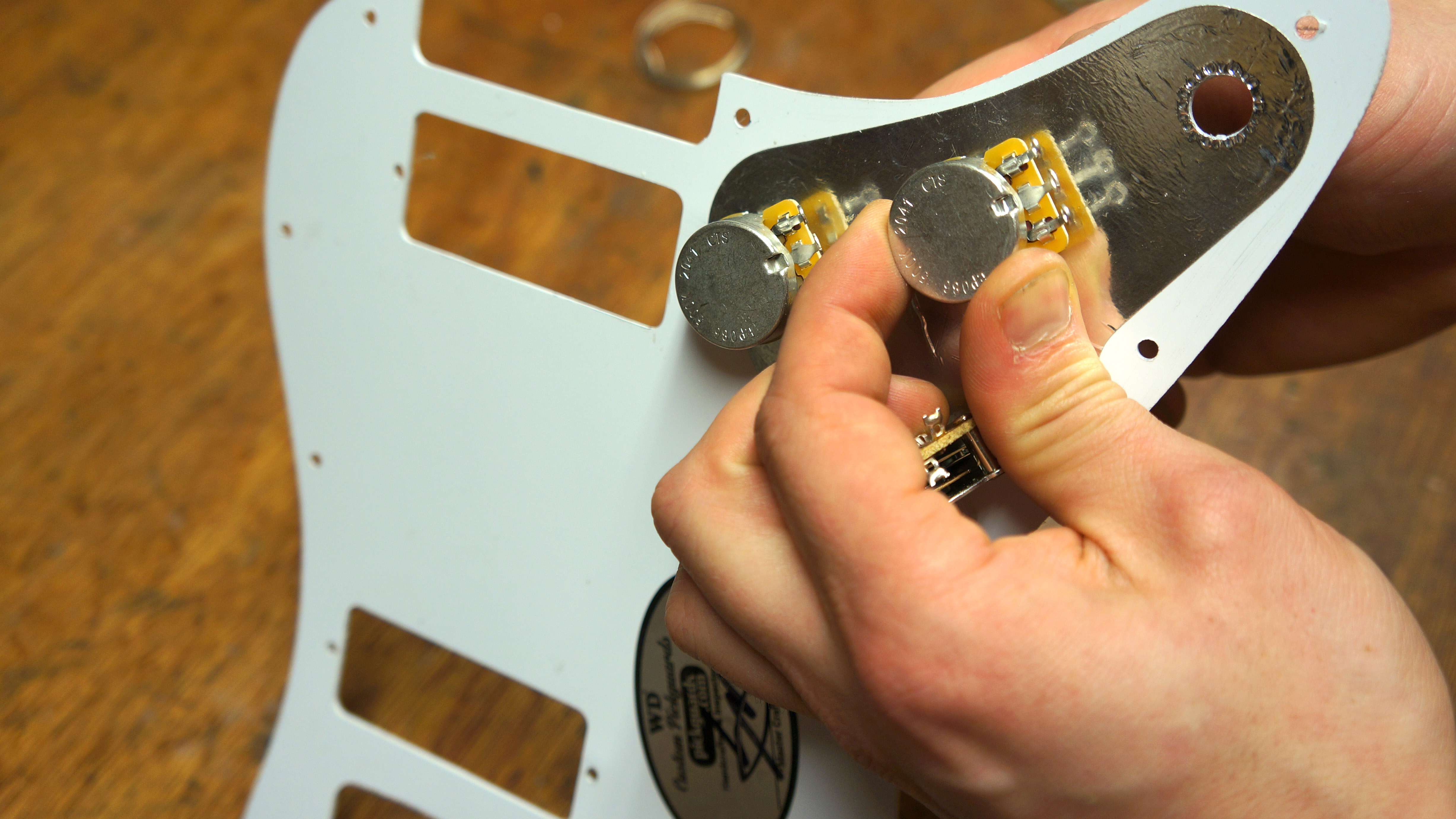
Fit the pots this way round so that the terminals have less chance of touching the cavity walls of the guitar.
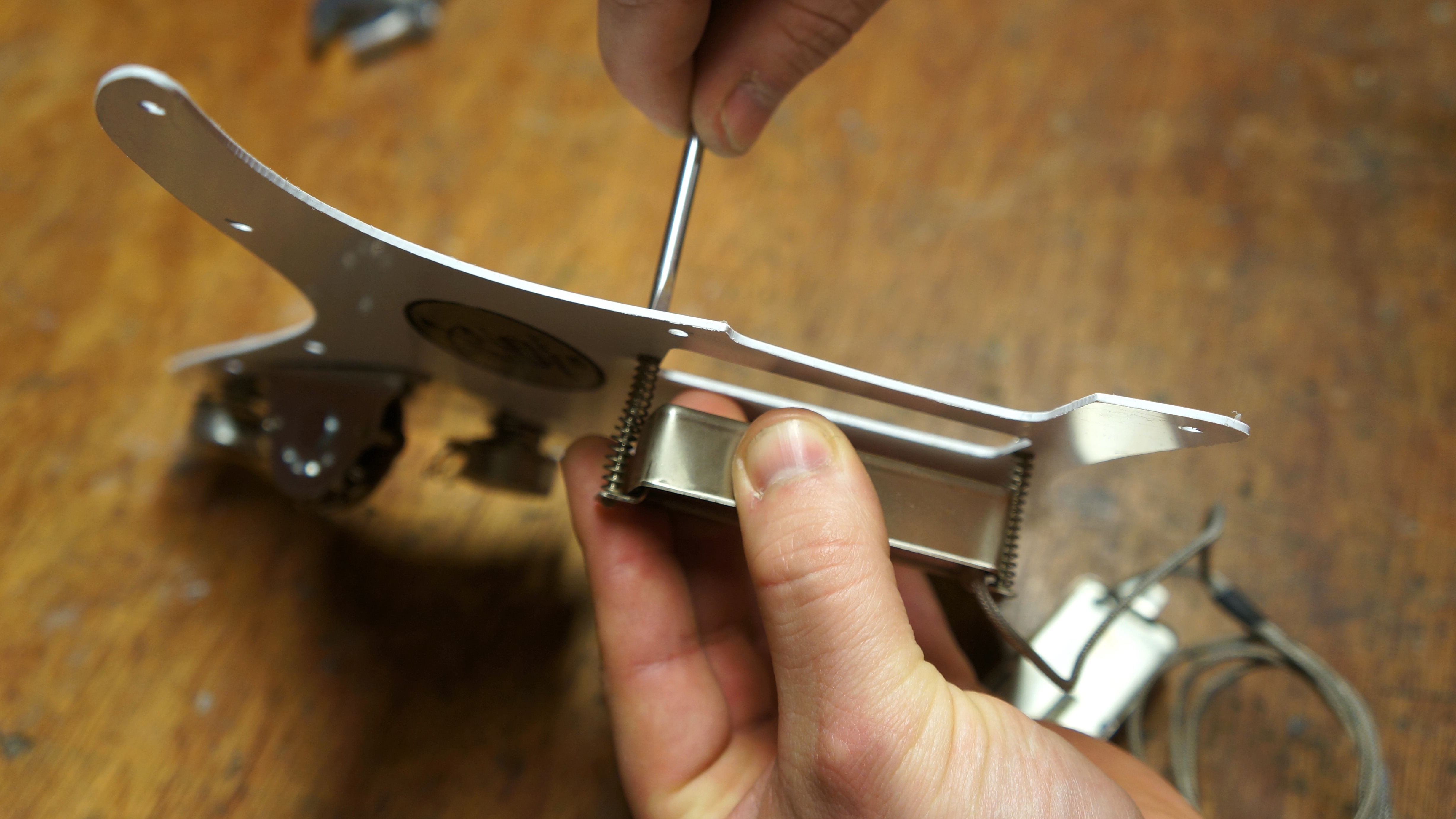
Load in the humbuckers, do your very best not to launch the pickup springs into orbit as they try to escape you…
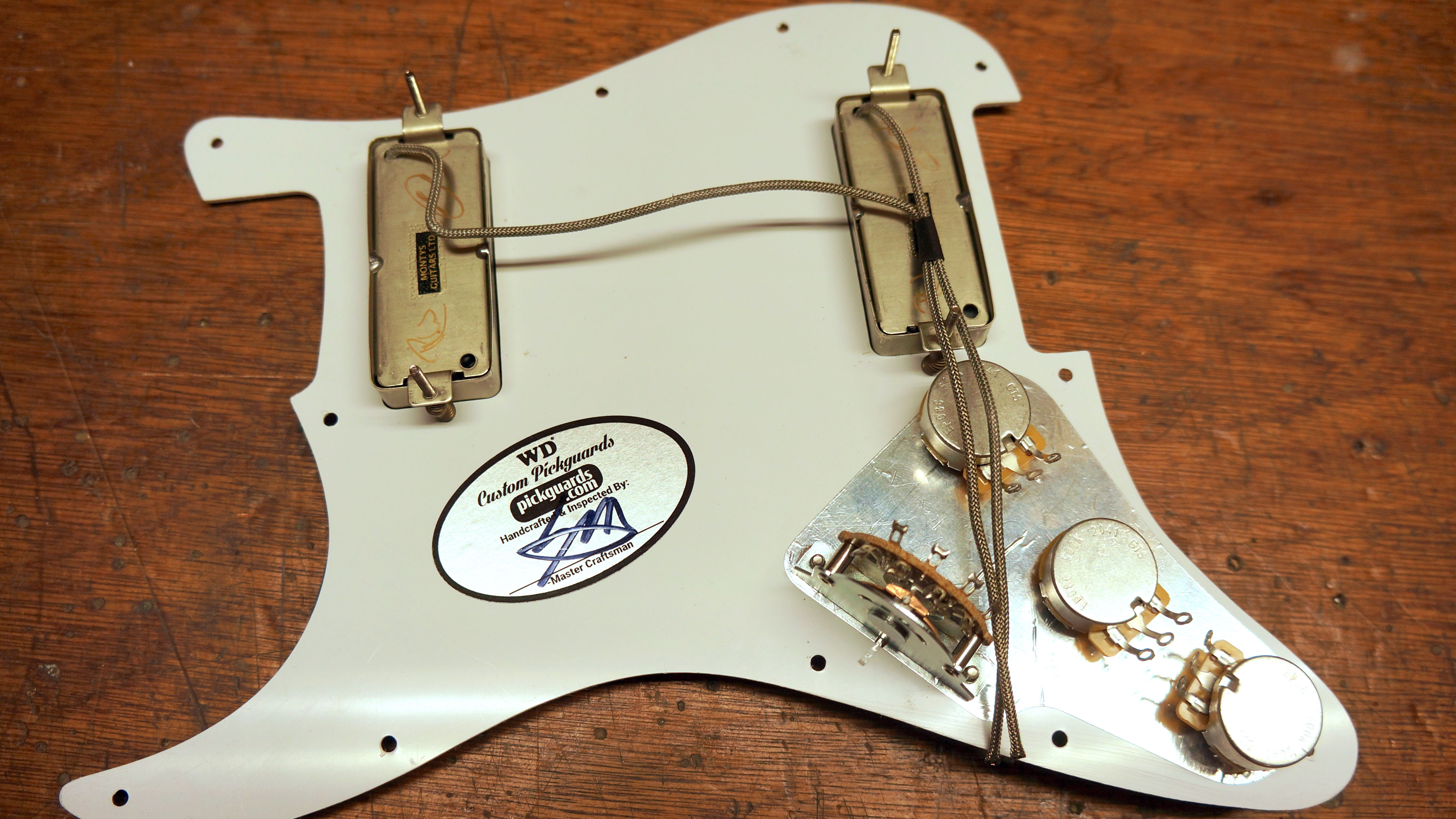
Here’s the parts laid out installed in the pickguard, terminals all facing the right way round. We’ve made a start on shaping the braided wire from the pickups too, this will make installation easier as well as once again making it look cooler…
Did you spot the shrink tubing on the braided wire? This will neatly fasten the wires together.
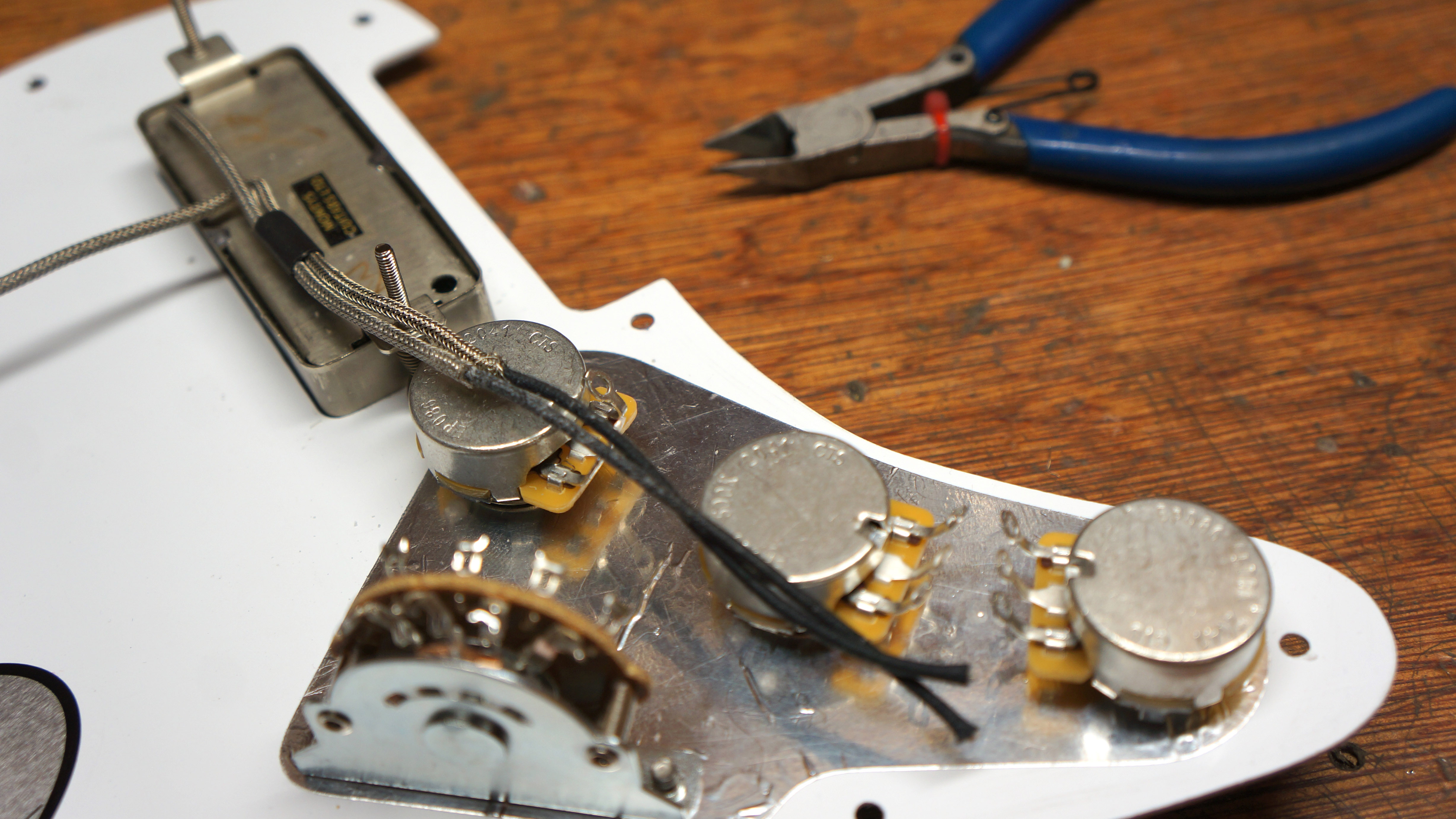
The traditional braided wire can cause trouble though, the bare metal of the braid is in fact grounded so if that touches anything that’s carrying a hot signal you will get a short circuit - and silence.
We’ve clipped back the braided wire so that the grounded braid doesn't go past the pots exposing the inner part of the cable which is black cloth covered wire - heat proof.
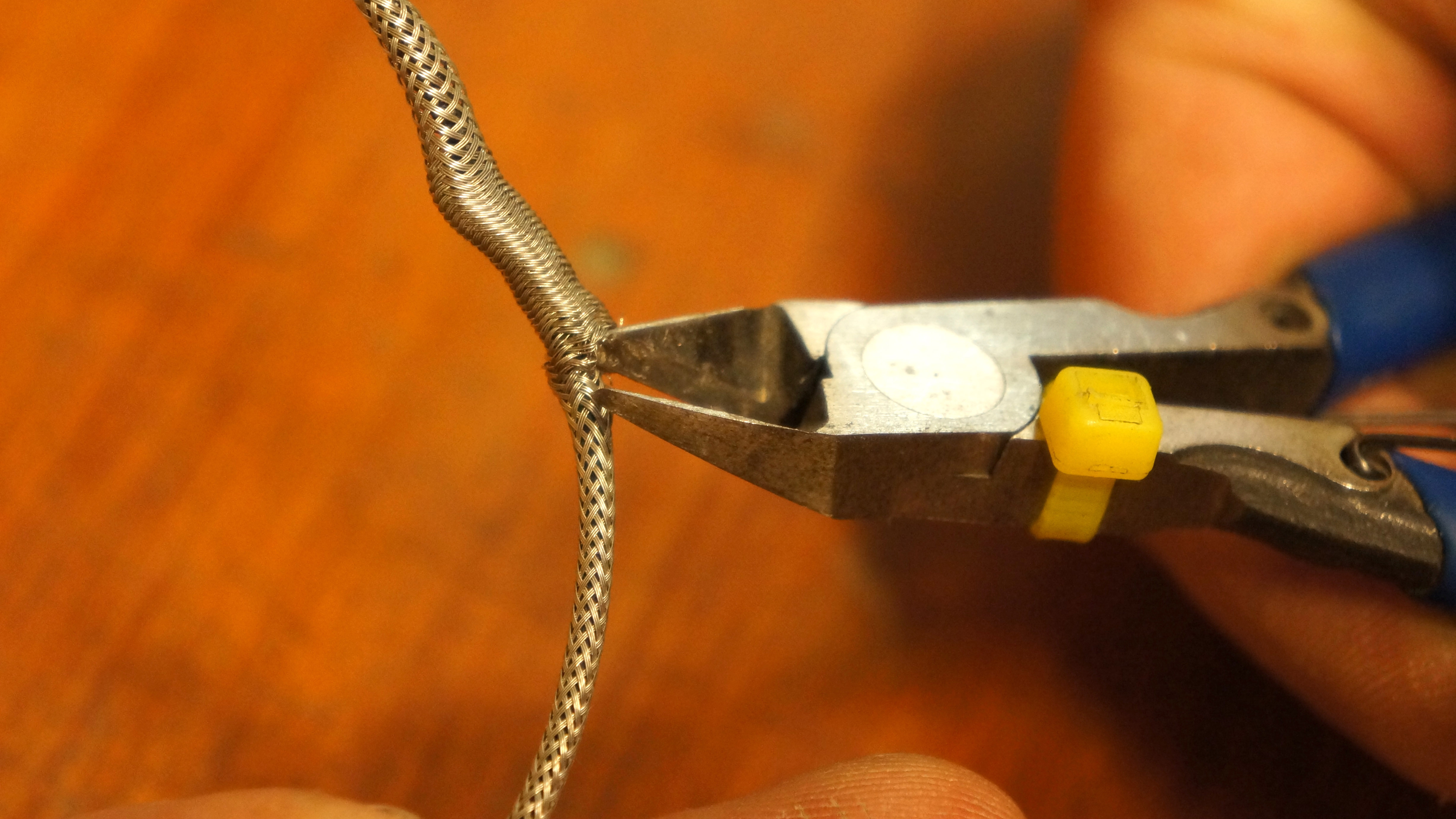
Here’s a great tip for how to de-braid easily, push back the braid just short of where you wish to retract it to and bunch it up.
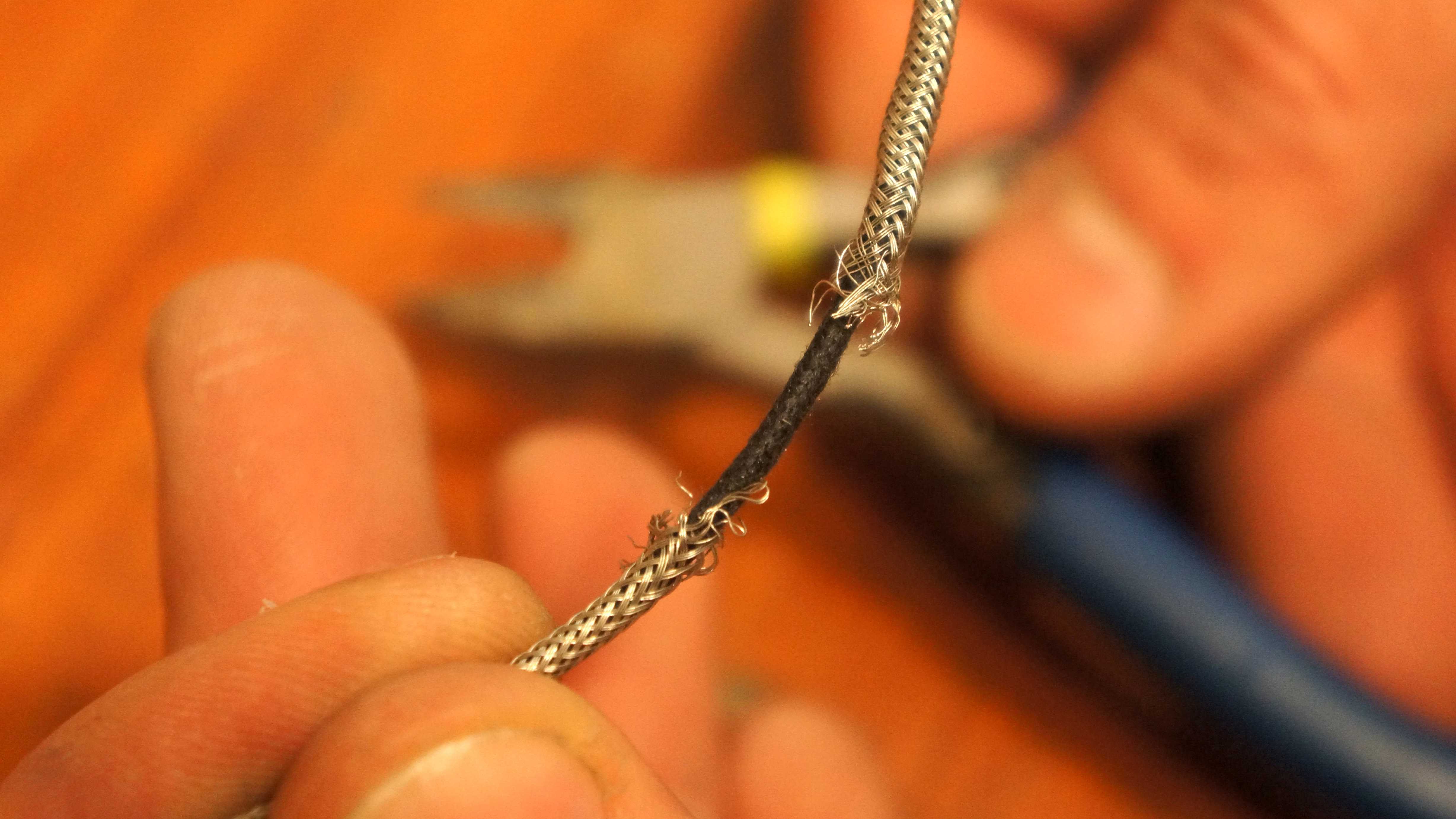
This will create a bulge in the braid, you can snip that bulge off and break the braid away without having to unravel loads of it!
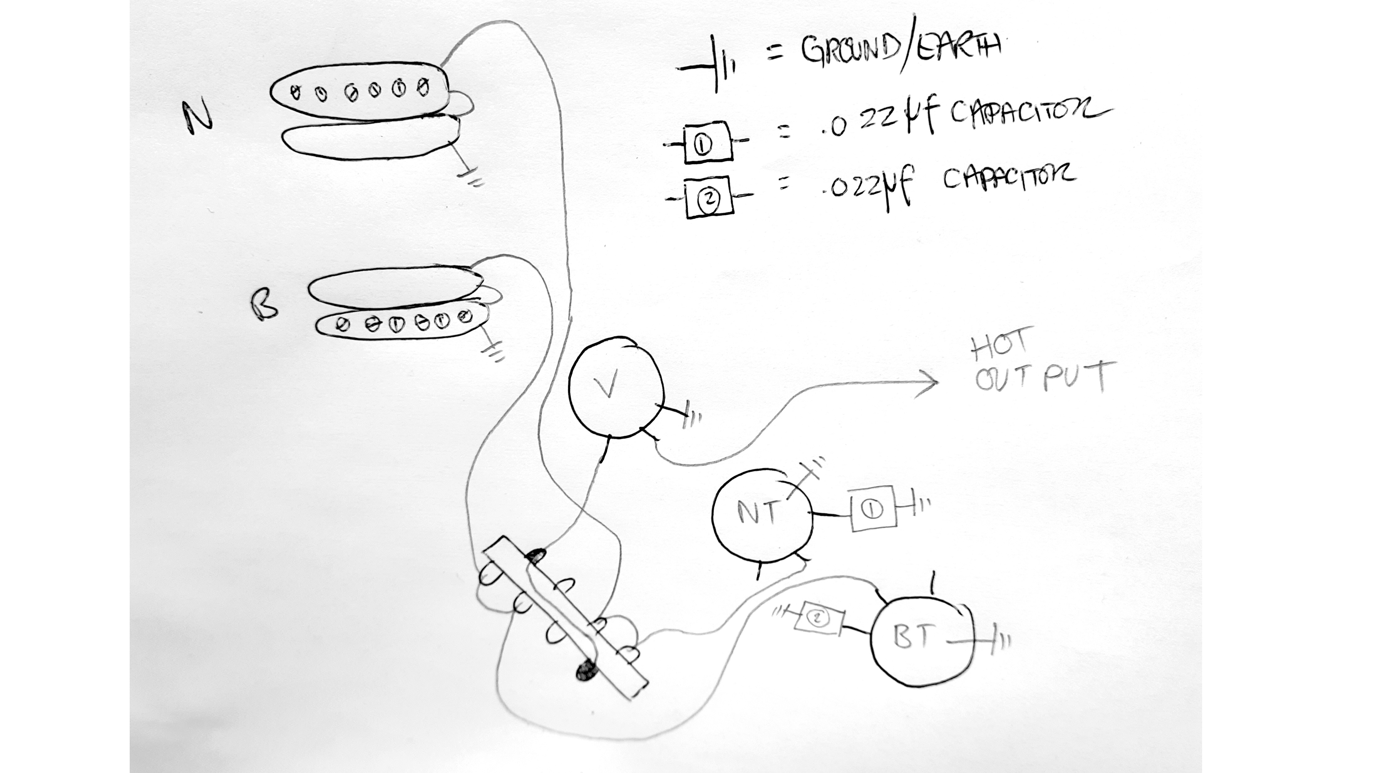
Diagram study time, the trick will be to break this down into steps which we’ll help split up for you so that the circuit is finished systematically.
Imagining the signal runs one way you can trace the signal using this flow diagram:
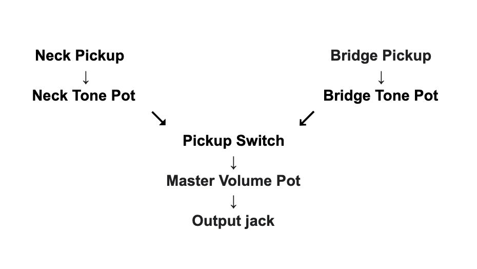
There’s ground wires connecting nearly every part up too but we like to hook those up later on.
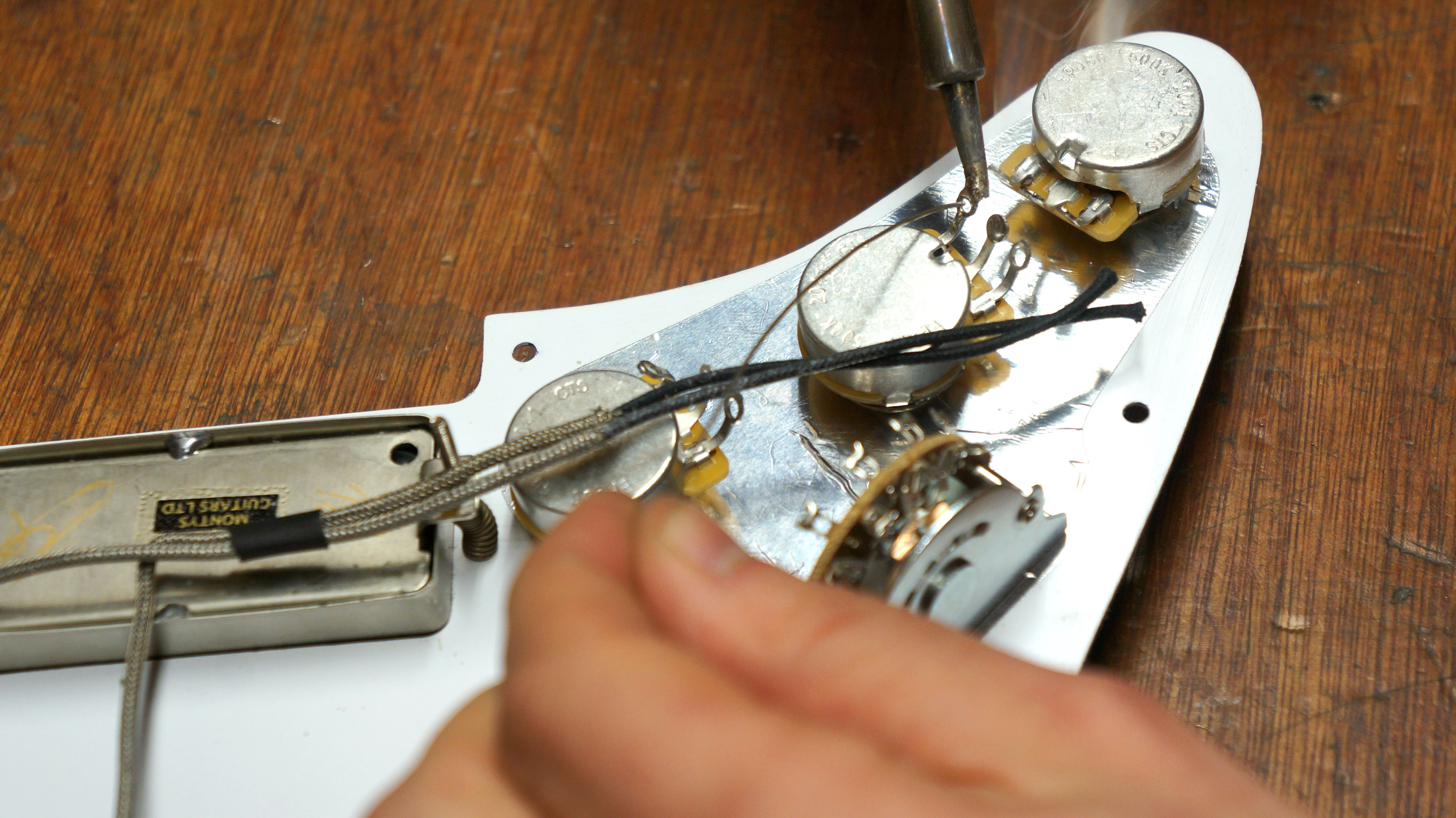
Now you’ve mastered the diagram you can begin to tin and prepare the components. Tinning is adding a small amount of solder to the surfaces that will be soldered, this step makes it much easier to make the solder joints later as you will not have to introduce solder whilst holding the iron and the wire.
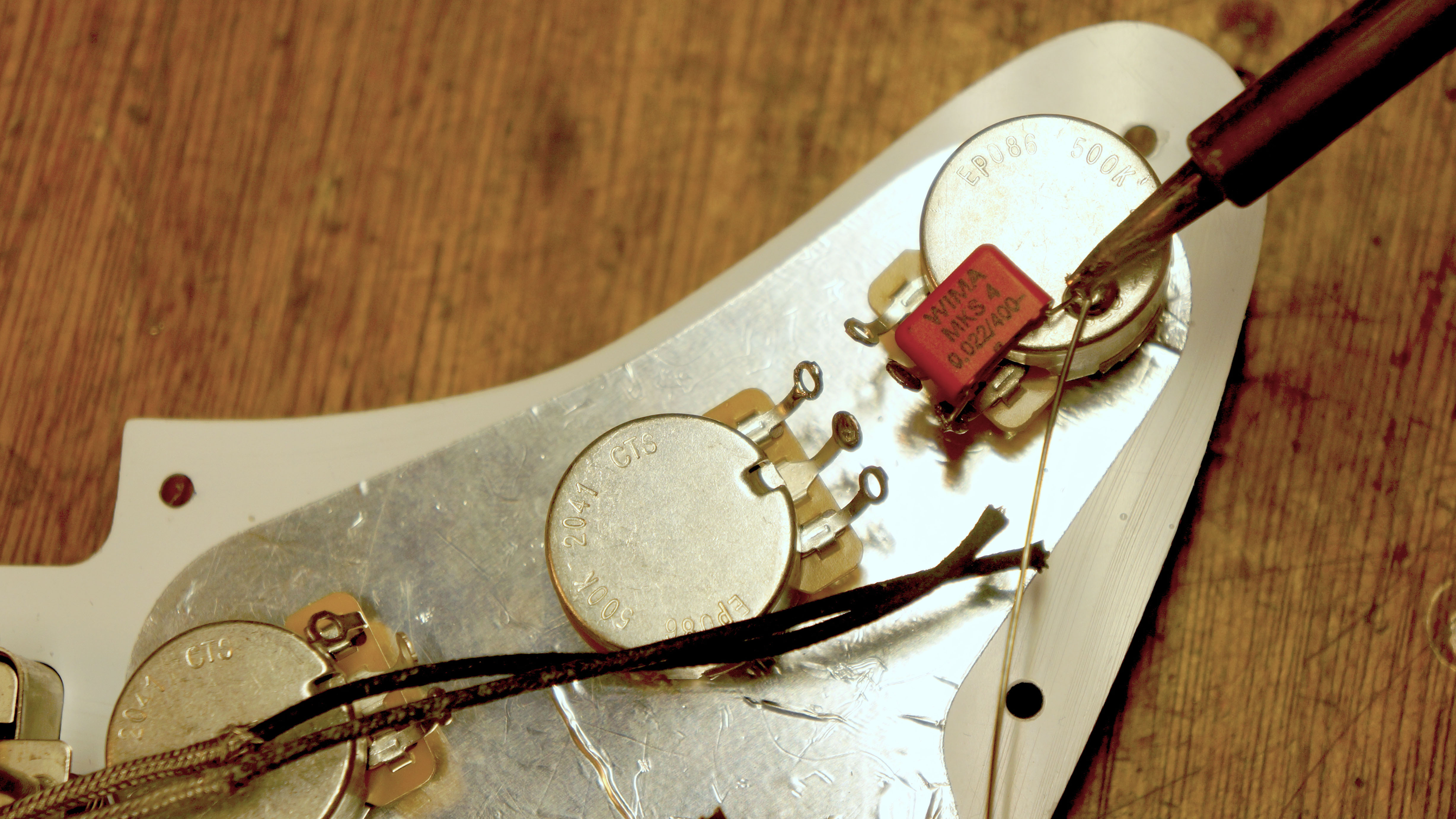
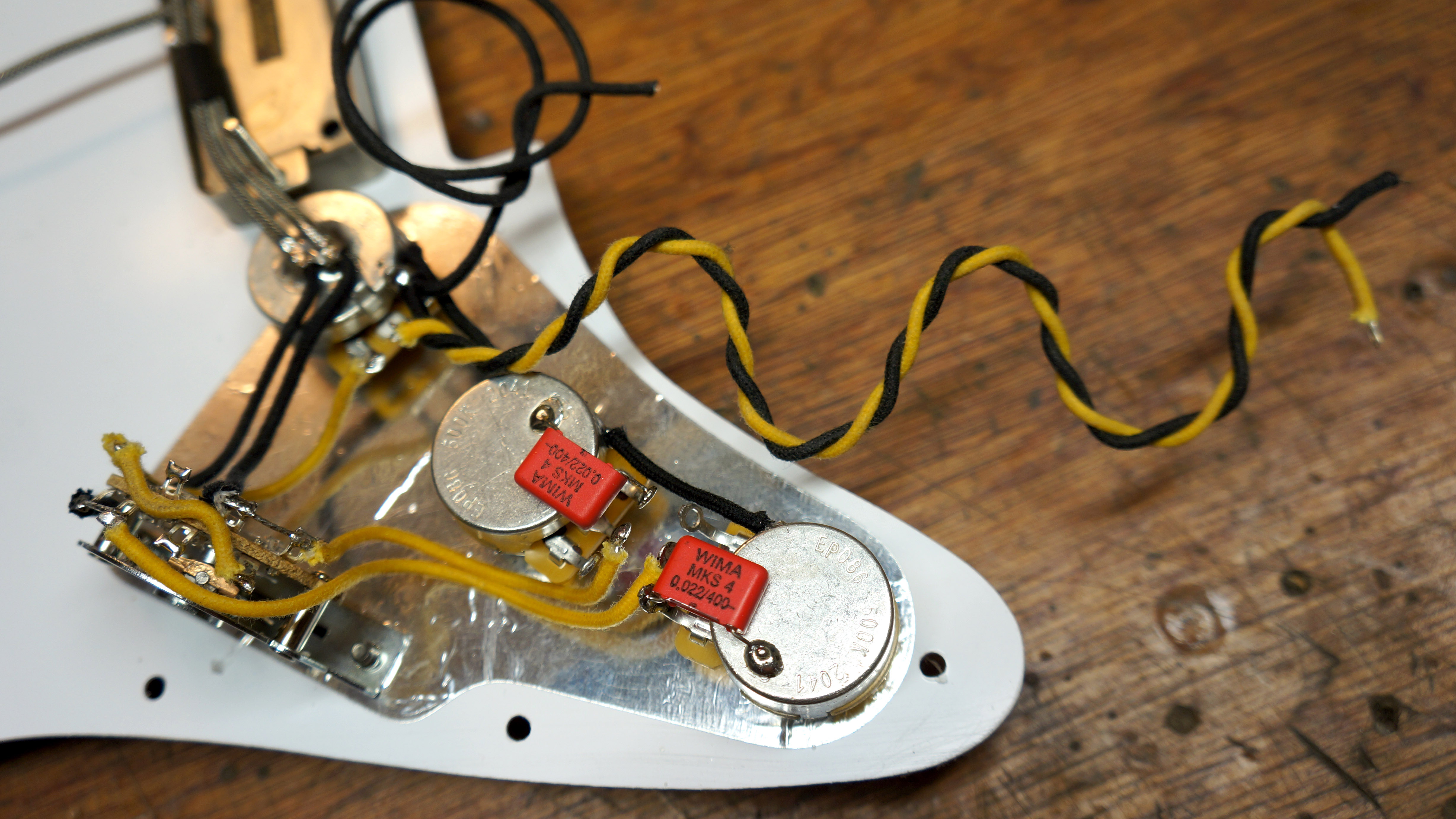
With the relevant terminals soldered, we can now add some fiddly components on, here were installing the tone capacitors onto the backs of the tone pots.
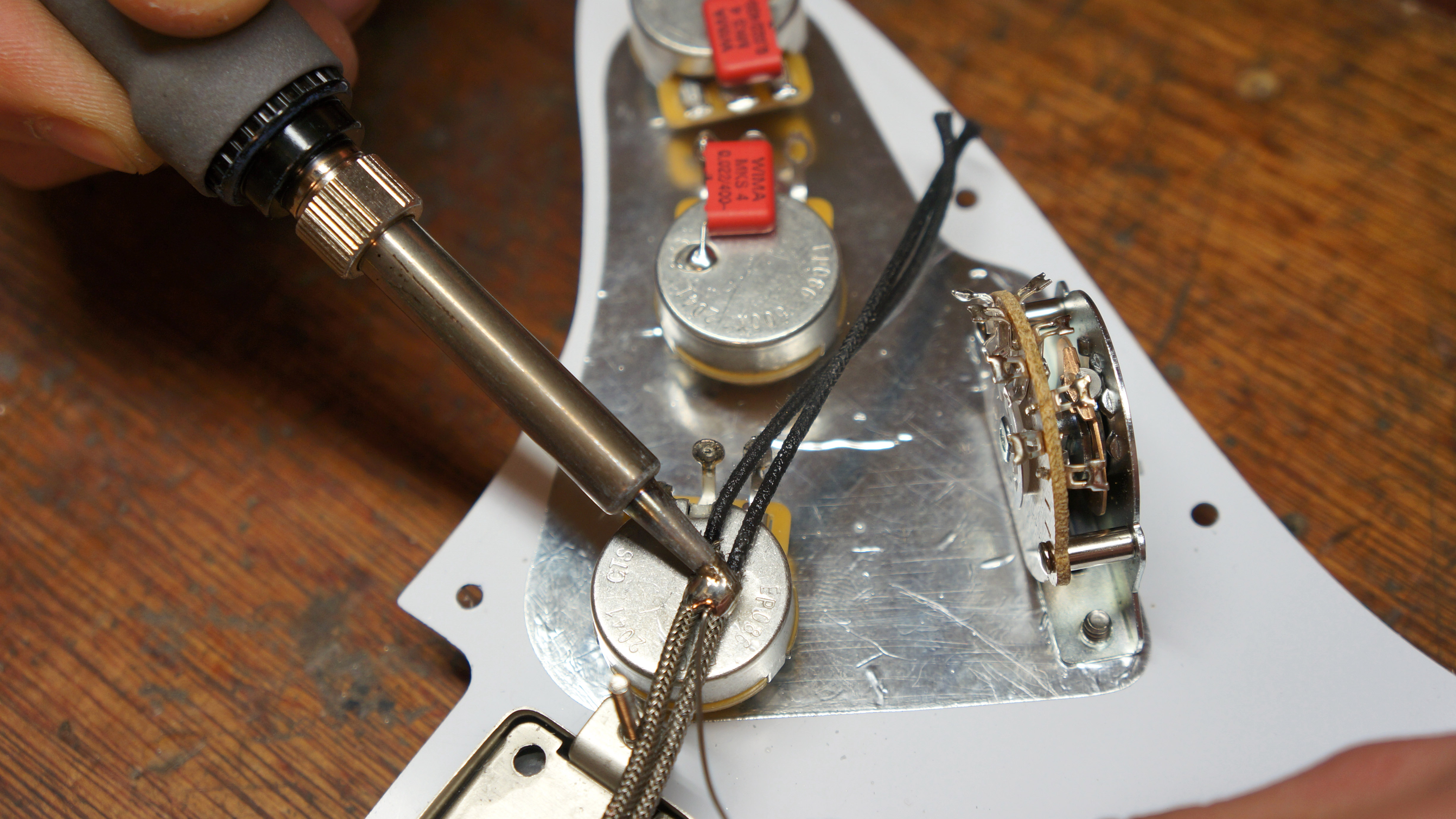
Time to fasten those great big braided wires, this is a Gibson technique but is only possible if you have the braided wire with cloth inside, the cloth does not melt! If you have plastic screened cable then this technique will simply melt through making a short circuit.
Heat up the wires for a good long time, a high powered soldering iron really helps here - 80 watts is great, flood in a heap of solder as these braid soak up loads. You’ll know when the joint is ready as the solder just pools nicely. This will be very hot so keep safe!
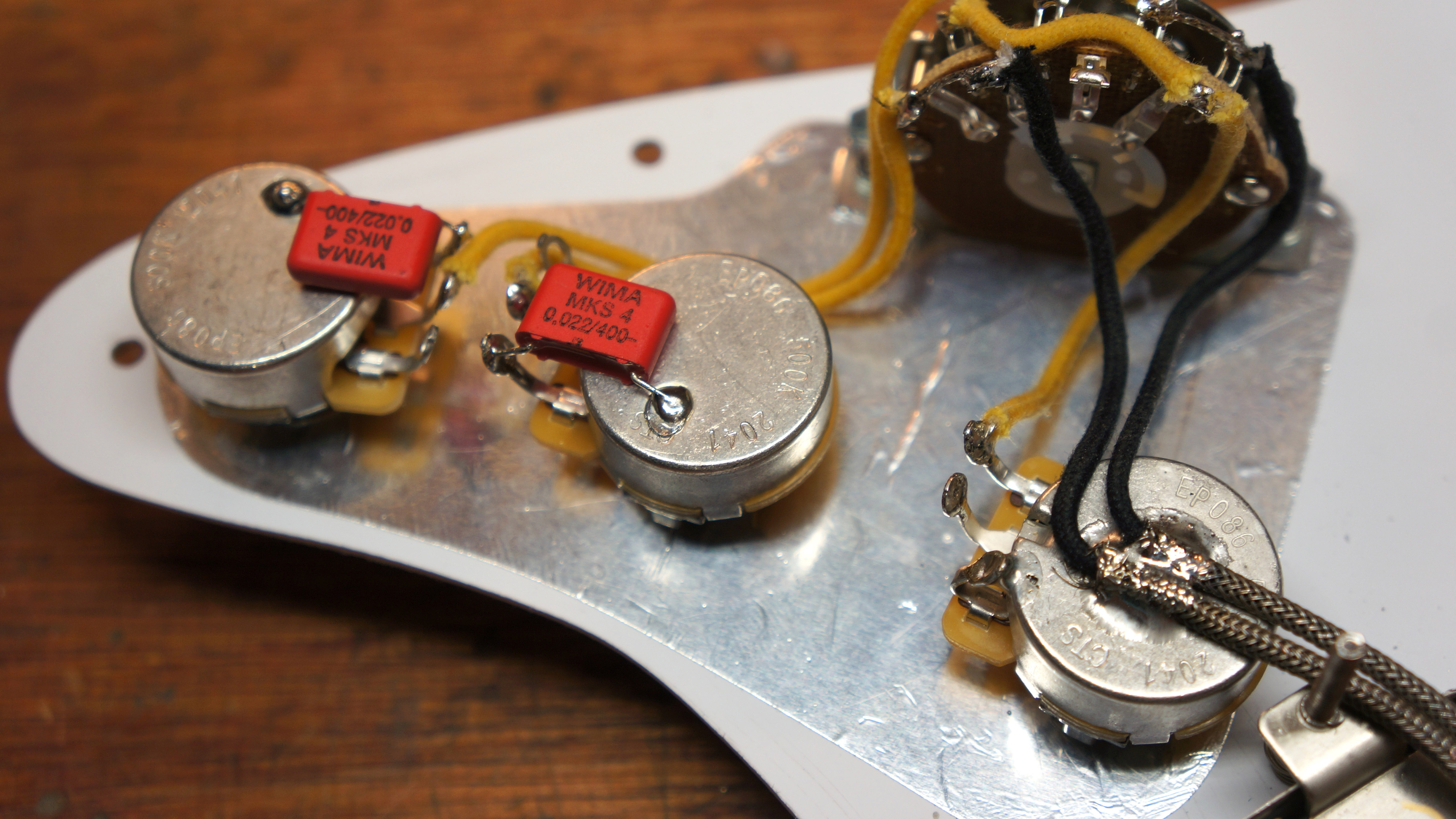
Basically, follow the diagram.. We’ve hooked up our pickups, jumper wire on the switch, tone pots and switch to volume pot wire too.
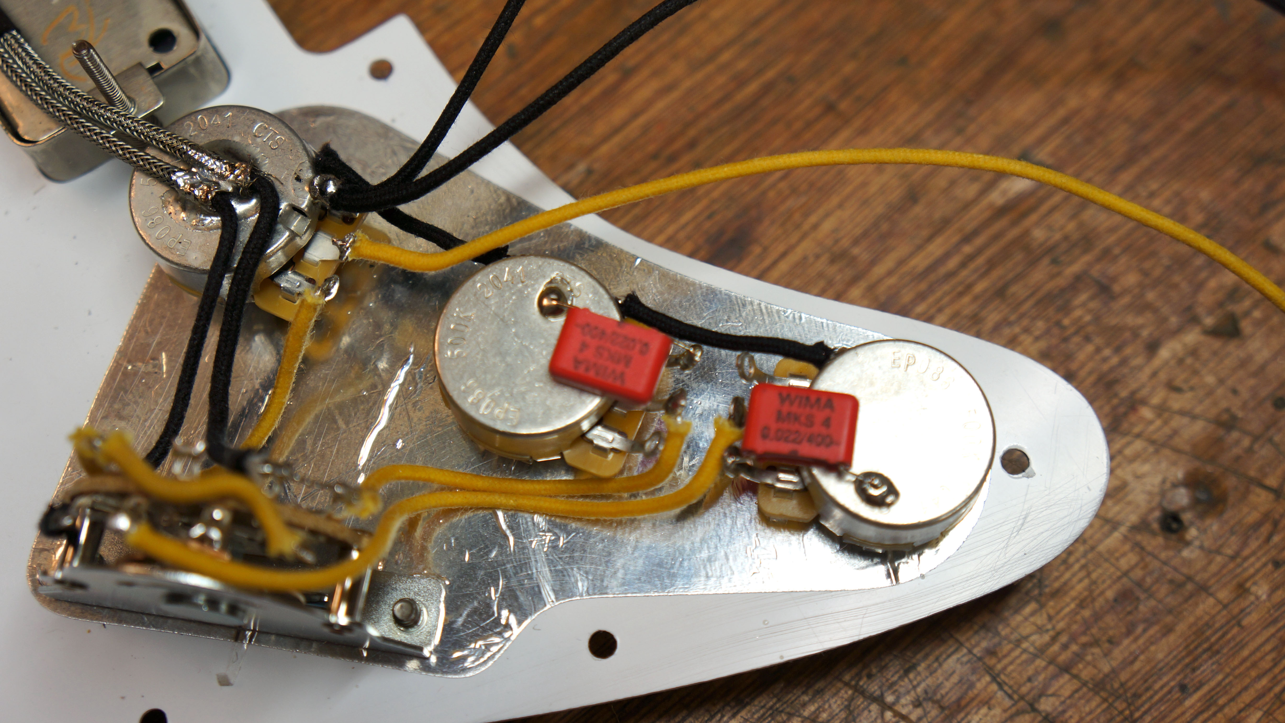
A couple more added, here’s the ground wires linking the pots together, master output wire (hot and ground) and a spare ground which will be soldered to the tremolo claw in the back cavity. That’s about it.
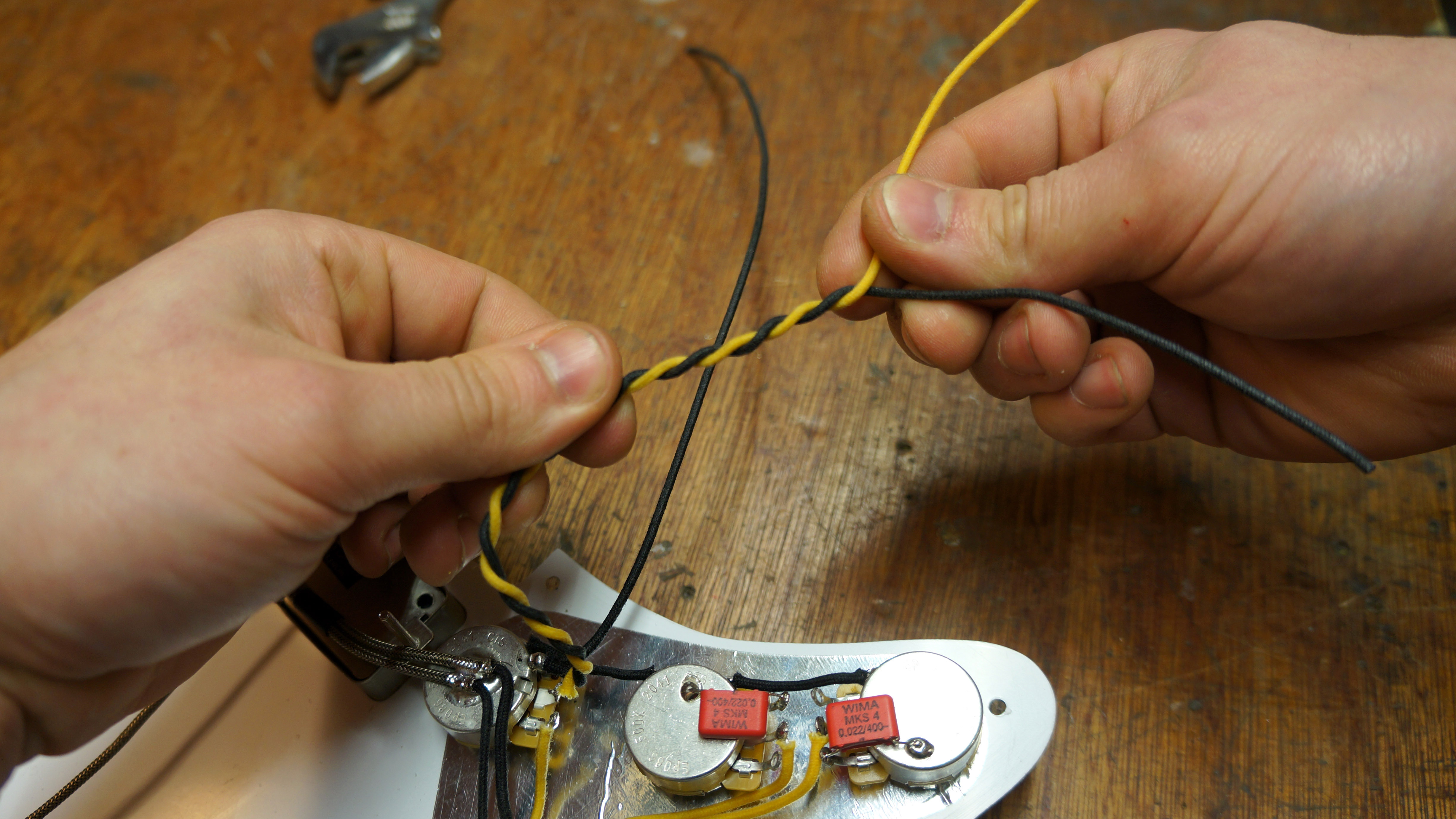
Now how do we make this wiring loom Instagrammable? Simply twist the wires together neatly…
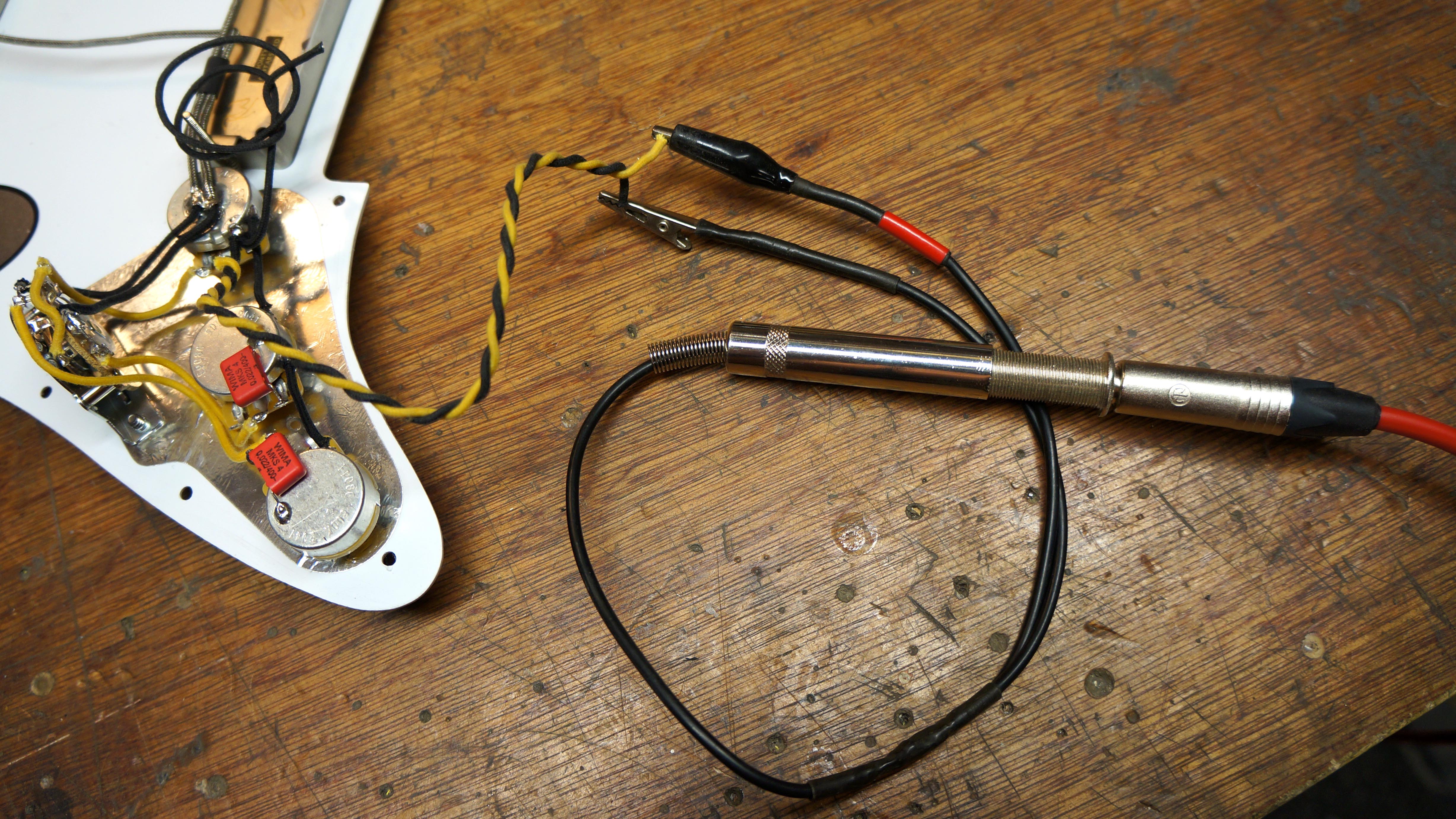
Before we get too proud, let’s test its function eh? We’ve made a cool tool for quick testing, two crocodile clips on the ends of a female jack plug - this allows you to clip into parts of circuits to hear them through the amp.
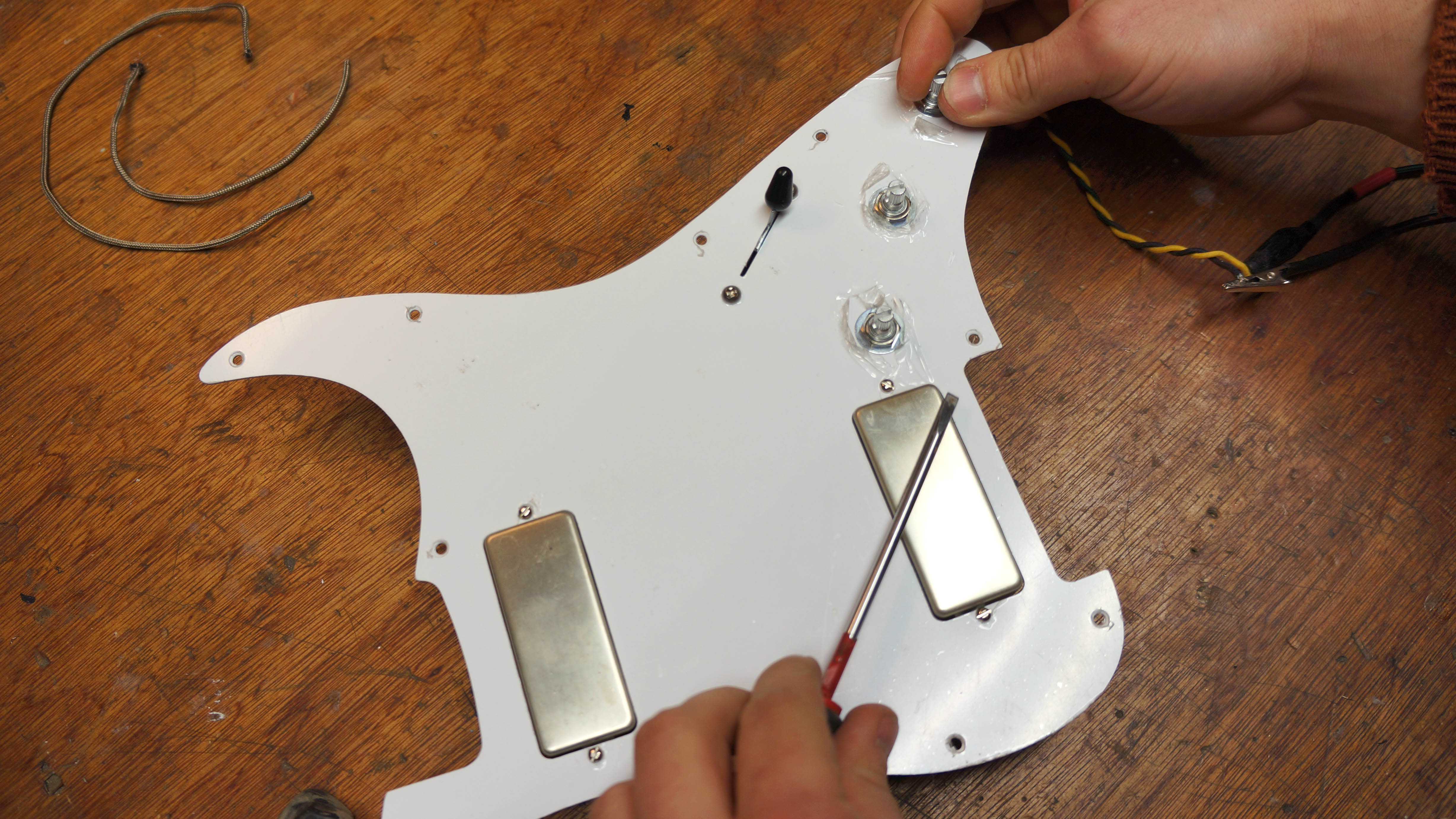
Amp on, test the pickups switch and pots by tapping the pickups lightly with a screwdriver. You can test for smooth taper of the volume and tone controls. The circuit will likely hum a little when off the guitars this will stop when you install it into a shielded cavity on the guitar.
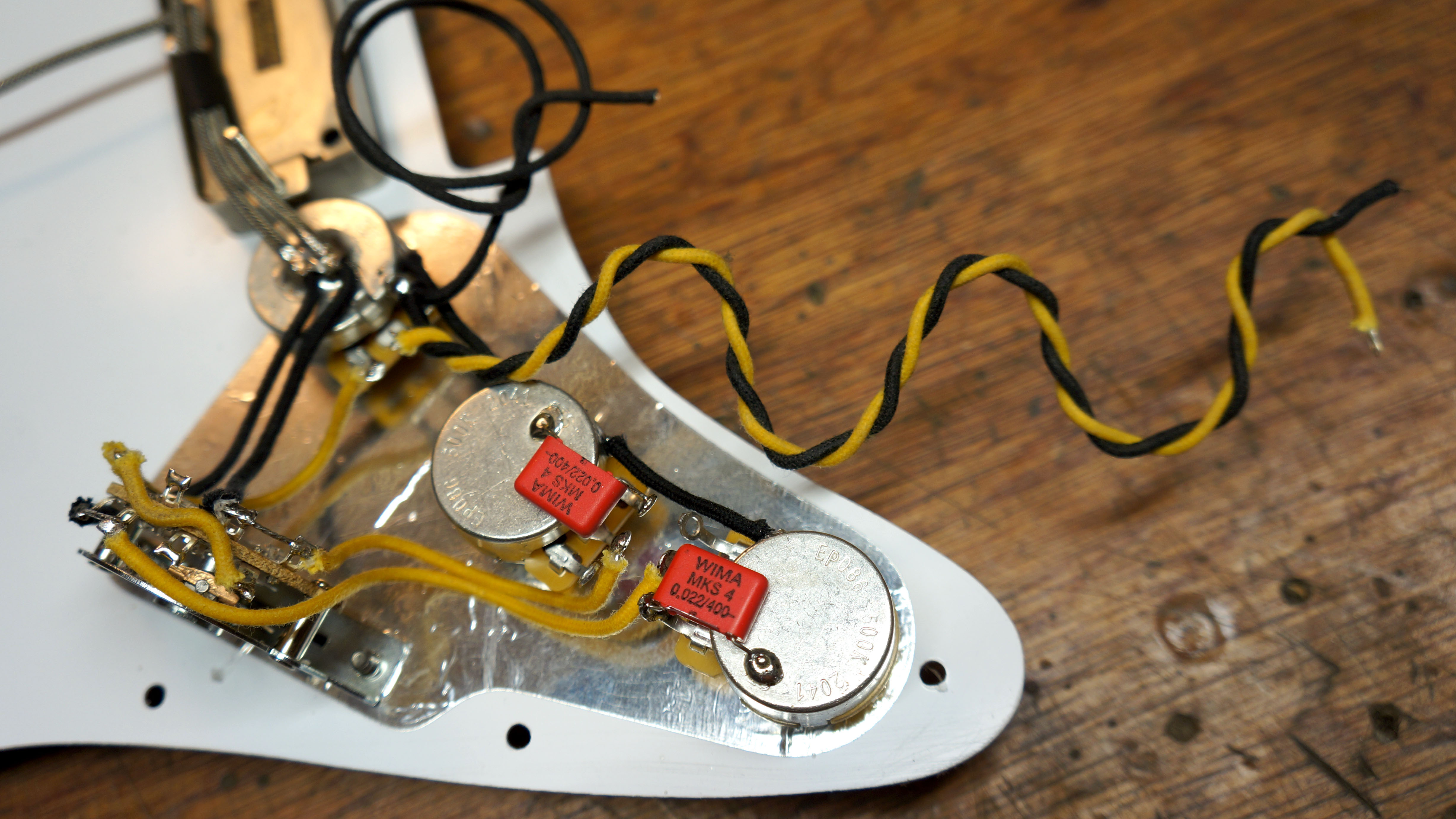
Now it’s ready to install on the guitar and handsome to boot (if you ever look under the pickguard).
How to adjust a guitar truss rod
Jack runs an independent guitar setup and guitar repair service in Manchester, England. He serves the musicians of the Northwest of England, working on electric guitars, bass guitars, acoustic guitars and more. Jack has been writing the Fix Your Guitar column in Total Guitar Magazine since 2017.
