How to replace a Telecaster pickup switch
Swapping out a faulty pickup switch needn’t be a dreaded chore with this guide
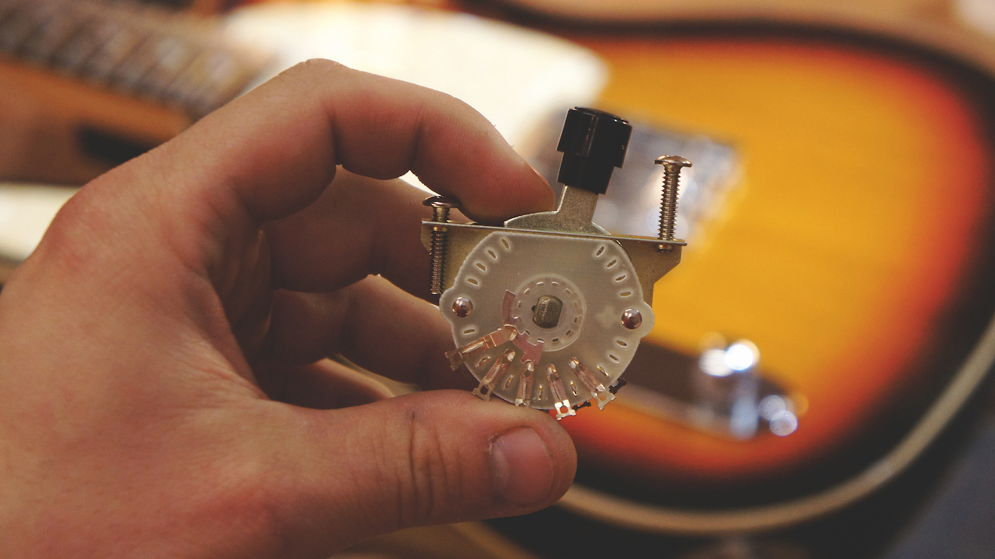
It seems we’re always swapping out knackered electrical parts here in the workshop; the combination of electric and mechanical wear is just too much for some guitars over time, especially when they’re subjected to life on the road!
Jack sockets, pots and switches all need to be looked after regularly but in this case this Telecaster’s switch is not clicking into position and the top’s bent too.
But this is a four-way switch that’s a little different to the factory standard three-way unit. When wired in correctly it will give you four positions: bridge, bridge and neck in parallel, neck and finally neck and bridge in series.
That last selection is an especially nice boost effect with added warmth that the Tele pickups can lack. Think humbucker! Be wary that it’s not always okay to trust the old wiring, especially if someone’s been at it first, so it’s essential that you find a decent wiring diagram for this. The Seymour Duncan wiring diagrams are great and we also like the ones on guitarelectronics.com.
What you need:
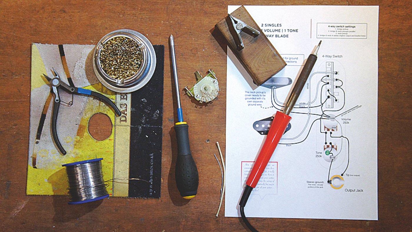
- 40-watt soldering iron
- Solder
- Safety glasses
- Protector mat
- Soldering iron cleaning tool
- Incredibly handy soldering clipboard
- Wire cutters
- Spare wire
- The right wiring diagram from a reputable source
- New pickup switch
Step 1
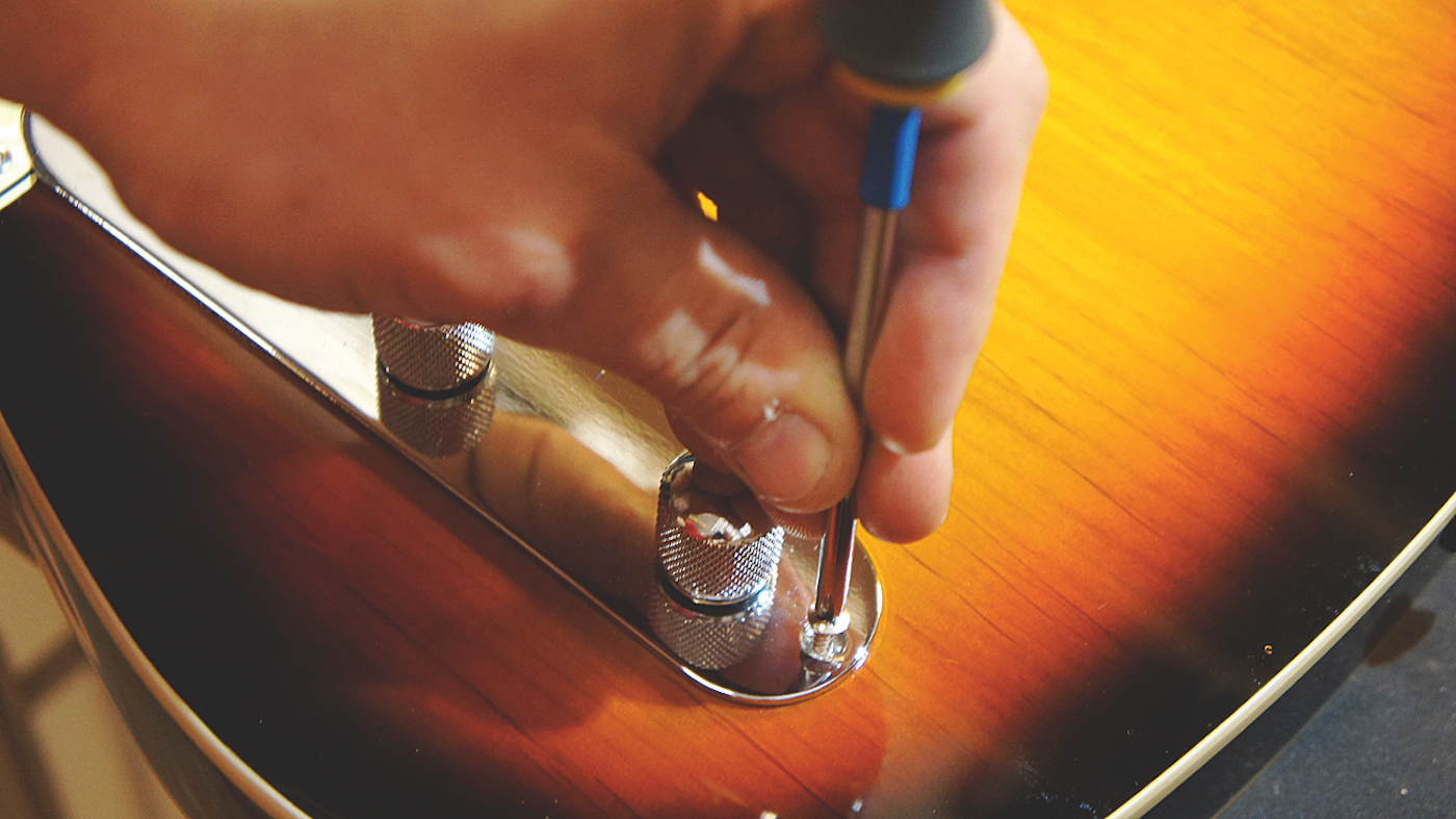
This switch is done for - with the new part in hand, let’s swap it out. Step one: gain access of course! These two screws fasten the very handy control plate making the Tele an easy patient. Put these screws somewhere they won’t roll away and go missing...
Step 2
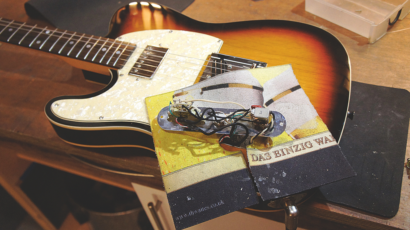
Carefully extract the guts. Don’t pull anything too hard as it may disconnect - it’s the control plate and pop the knobs into the recess for access but that won’t guard you from rogue solder blobs. We recommend a protector mat (pictured).
Step 3
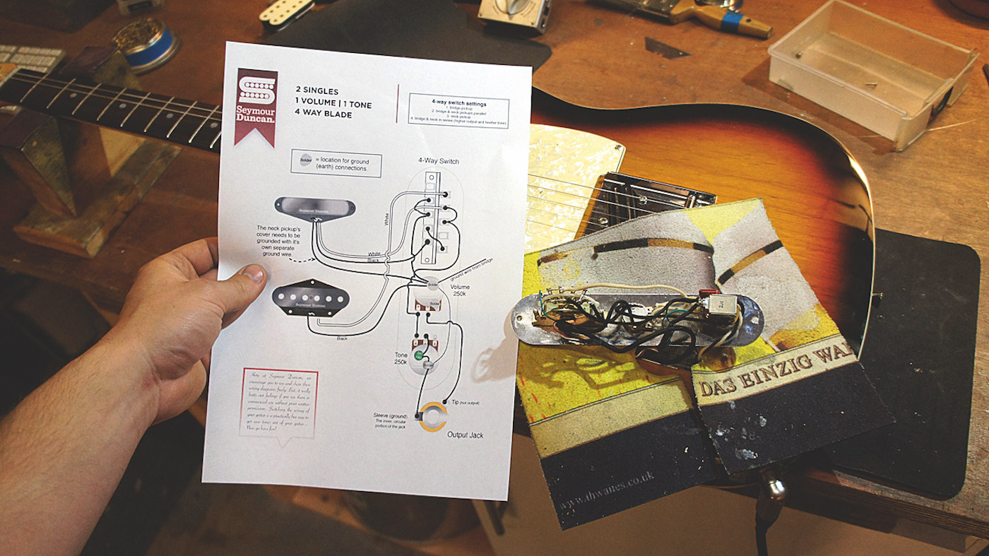
Before we tuck into soldering it’s essential to familiarise yourself with the wiring diagram. This circuit here is a custom four-way wiring one with some extra bits too. Cross reference the wiring in front of you with the diagram just to be sure no funny-business is afoot.
Want all the hottest music and gear news, reviews, deals, features and more, direct to your inbox? Sign up here.
Step 4
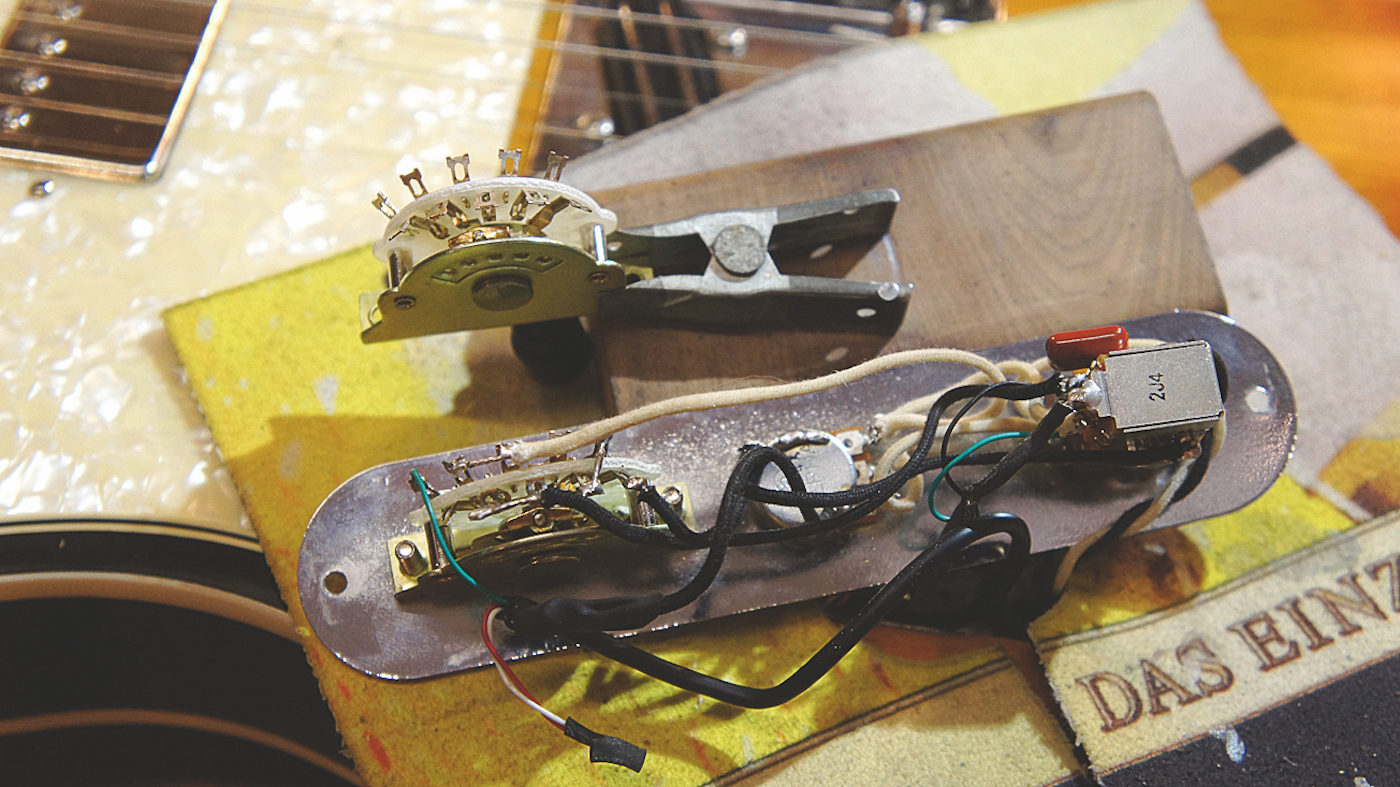
We love these clipboards for soldering, and it’s easy to DIY one for yourself too! The wiring diagram checks out with the switch so with the replacement part alongside the old it will be easy to swap over one wire at a time. Nice, easy and methodical - the best way to approach wiring.
Step 5
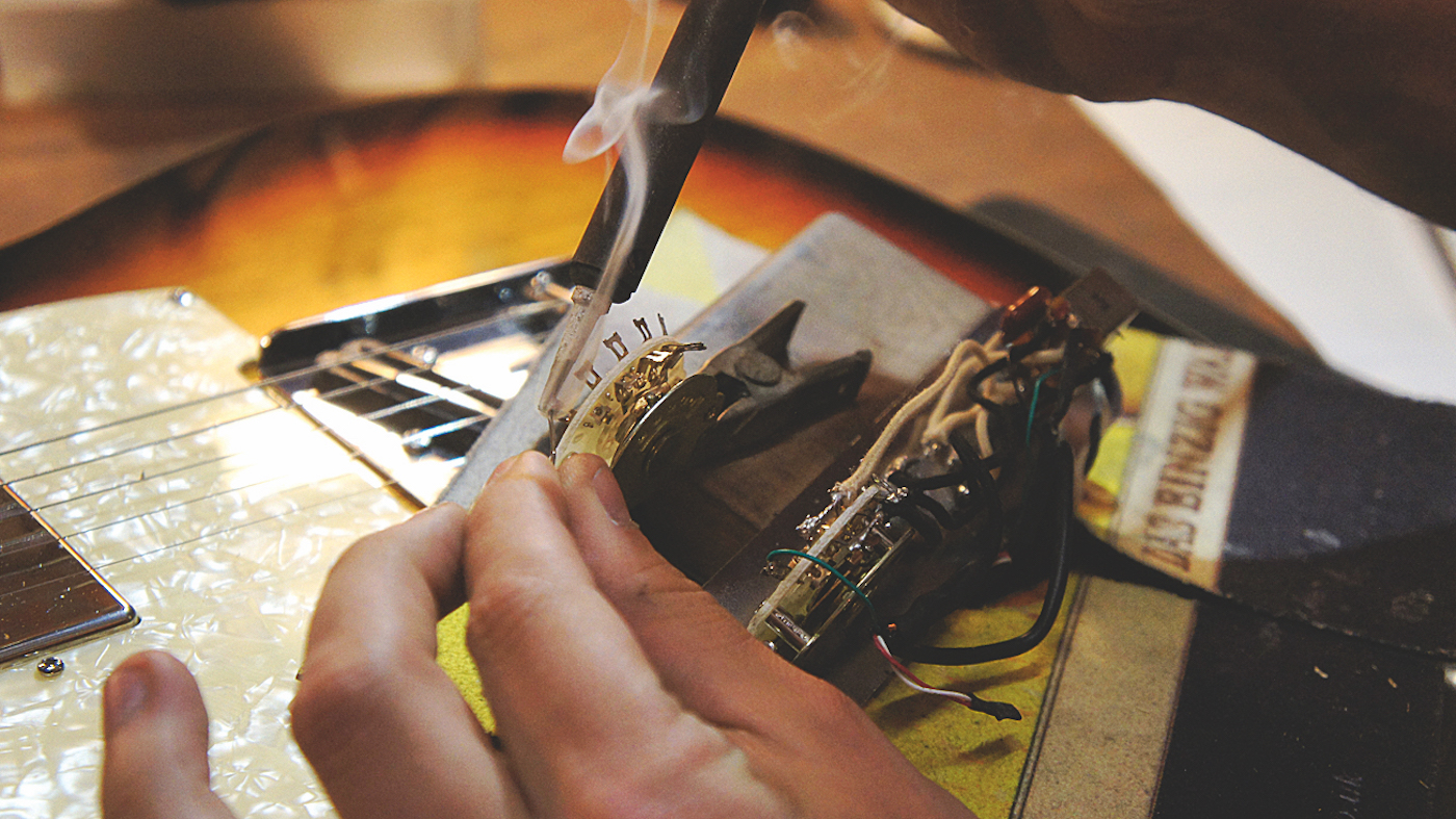
Position the switch the same way round as the old one and tin the terminals that will be used. Tinning the terminals on the switch is preparing them to accept a wire. Be careful not to add too much; if you do, the excess solder can run down into the workings of the switch and mess it up - you’d have to buy a new one. all too common to find botchery in there. You can, if the wires are long enough, flip the control plate and pop the knobs into the recess for access but that won’t guard you from rogue solder blobs. We recommend a protector mat (pictured).
Step 6
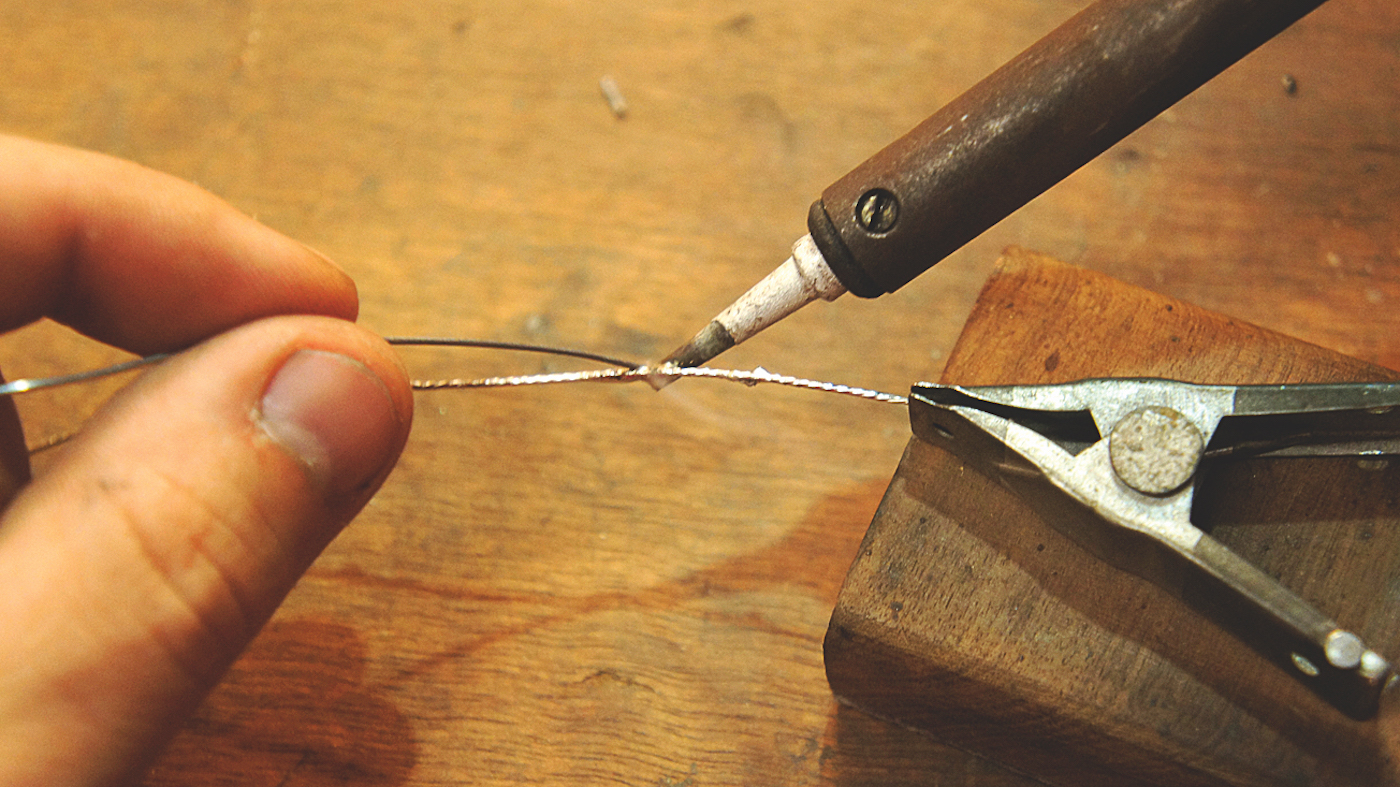
The switch for the four-way wiring has three jumper wires between the terminals. Let’s prep this first. Using some spare wire, strip back the jacket to expose the bare wire. With this in a clamp, tin the bare wire too. Tinning it means you’ll just have to melt the wire and terminal together without needing a third hand for solder!
Step 7
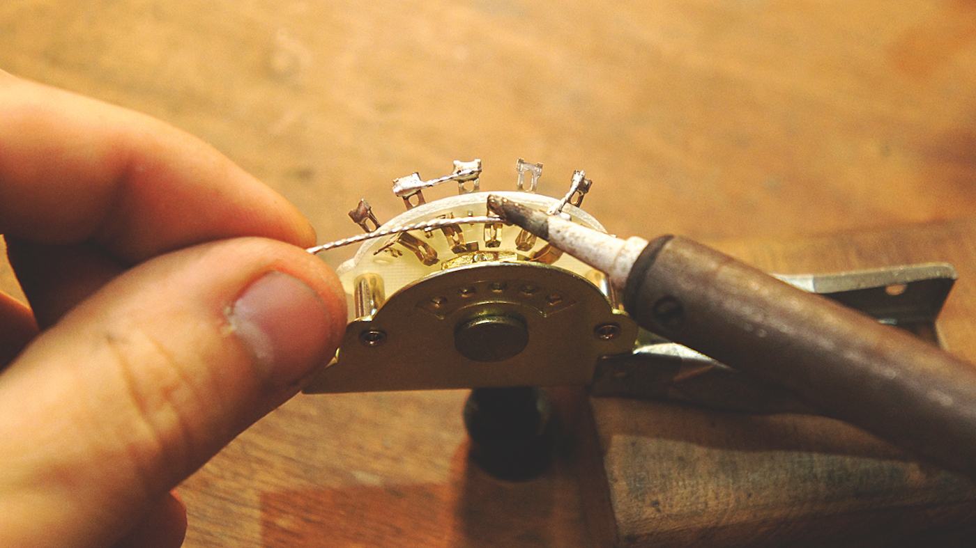
Double-check the diagram then preheat the terminal with the soldering iron to melt that already tinned terminal. When it gets to the right temperature it will liquefy - then you can press in your jumper wire nice and easy. Every now and then add a teeny tiny bit of extra solder to make it look a little better if you think it’s necessary.
Step 8
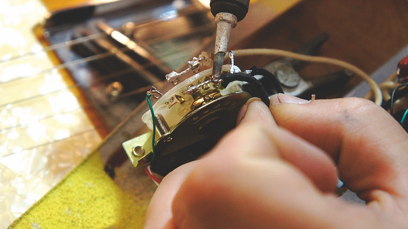
Steady as you go, transplant one wire at a time. Make sure you count the right amount of terminals so that each wire goes where it should - check the diagram for reference if you get lost. It always seems that the phone will ring whilst in the middle of this but stay on target! Don’t excessively tangle the wires up as you go.
Step 9
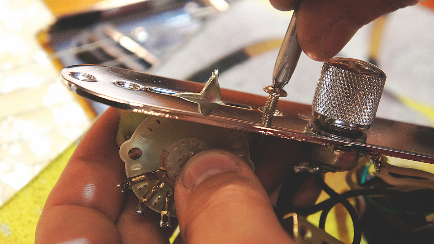
Righty, that’s the last wire transplanted so let’s take off the old switch. It’s pretty clear to see why this one needed swapping. In fact, we needed to straighten the bent part to let the old one out! Pop in the new guy in its place and tighten the two bolts up.
Step 10
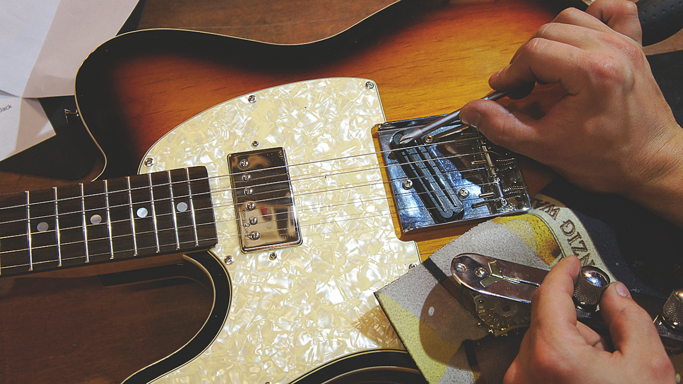
Before we get carried away and put it all back together, it’s a good idea to test the circuit now. Use a screwdriver to gently tap on the pickup’s pole pieces when plugged into an amp. Check all the switch functions and pots too. If a strange thing happened, dive back into the diagram and see if a mistake has been made.
Step 11
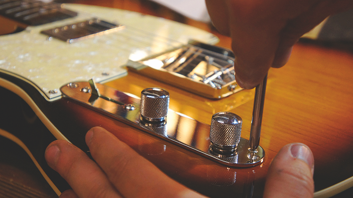
Now it’s time to reinstall the control plate. The reason why we tested it guts out is because this guitar has foil shielding in the cavity. The foil reduces hum in the circuit but is conductive; if a second test shows a problem when installed it must be part of the circuit accidentally touching the foil - much easier to solve.
Step 12
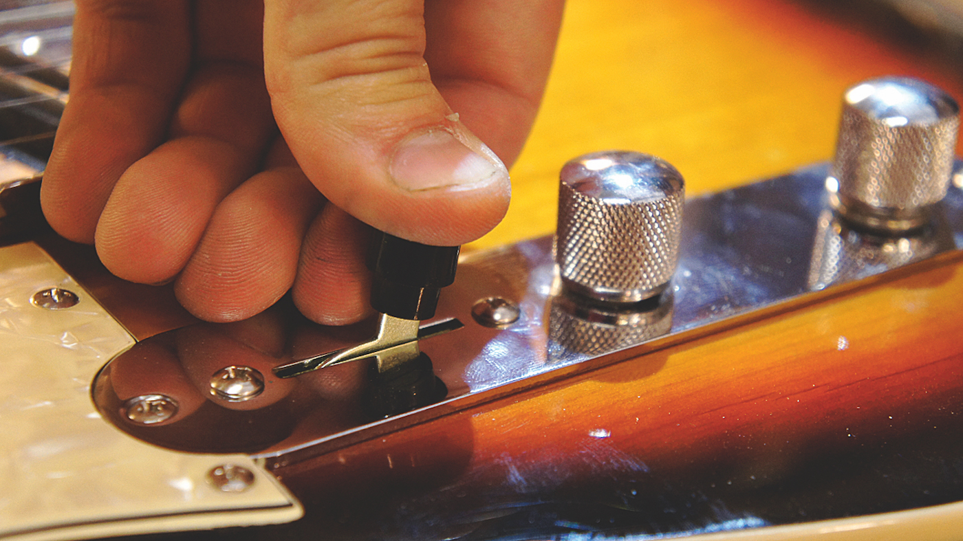
Well done champ, you get to complete the glory stage - push on the switch tip! If true glory is not possible it’s probably because the switch tip is a different size compared to the old one. A matching tip must be bought in this case and victory will be yours. We really wish they’d standardise those...
Jack runs an independent guitar setup and guitar repair service in Manchester, England. He serves the musicians of the Northwest of England, working on electric guitars, bass guitars, acoustic guitars and more. Jack has been writing the Fix Your Guitar column in Total Guitar Magazine since 2017.
