In this age of hand-made, boutique gear (not to mention the enforced confinement), many guitarists have taken up soldering irons and built pedals and equipment of their own to scratch a particular sonic itch.
But given the cost of hand-wired or point-to-point tube guitar amplifiers, you might wonder if building one is actually realistic.
The answer is that building a hand-wired tube amp is within the reach of most players. That said, the advice online can be somewhat difficult to make sense of, given the breath of options, and differing levels of experience among DIY builders.
Building an amp can not only be a fun project, but a good way of learning about electronics, how amps work, and also how to service other valve amps you might already own. It's a great way of building confidence and opening the door to other projects like constructing guitars, pedals or other studio equipment.

• The best guitar amps
• The best guitar amps under $1,000/£1,000
• The best budget guitar amps under $500/£500
• The best high-end guitar amps
So, armed with some experience of soldering pedals we decided to take the plunge and build a small tube amp using a kit from Barry at UK-based Ampmaker. It's worth stressing that many people who undertake this kit have much less prior experience and get through it mishap-free.
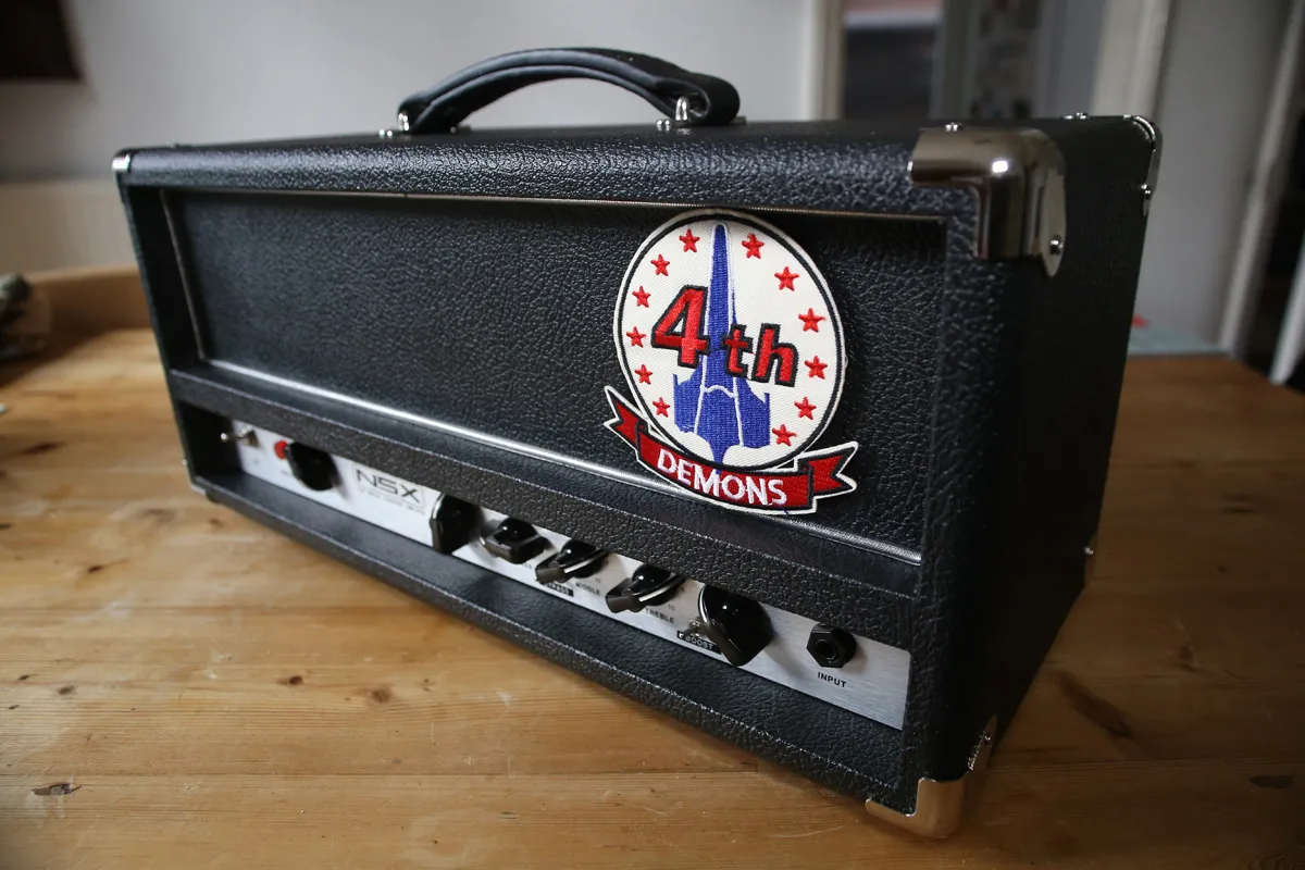
The N5X that we've chosen is a British-voiced, single-ended five watt head with a useful variable voltage circuit to bring the amp down from its surprisingly beefy maximum volume back to room level.
Although apparent volume is a fraught and somewhat subjective thing, taking a very rough rule-of-thumb of a fifty-watt amp being double the volume of a five watt amp - ignoring questions of clean headroom - five watts is more than enough power to be useful.
We're getting ahead of ourselves though - on to the build...
Before you start
So, first things first - if you're going to be undertaking an amp build then look online for advice on how to work safely with high voltages.
This is not an optional step - amp voltages can kill you, but with due care and attention, the risks are small.
If you've experimented with hobbyist electronics before then you'll probably know that even 9V DC is more than enough to melt a component and start a small fire, so the voltage in itself isn't the real danger, carelessness is.

Some digital multimeters aren't rated for more than 250 volts, so bear in mind that even on a five-watt amp like this, some of the test points are likely to exceed that. Either buy a higher-rated DMM or omit those tests.
Broadly speaking, you need to be careful about not turning the amp on when there are any grounds or short circuits, and making sure that after, for example, testing part of the circuit, you don't immediately resume work after turning it off.
First, safely discharge any large capacitors that store charge, or wait a reasonable interval before resuming work.


Tool-wise, here's what you'll need:
- Needle-nose pliers
- Wire cutters
- Wire strippers
- Good-quality solder
- Soldering iron
- Reverse-action tweezers
- A Phillips-head screwdriver
- A Digital Multimeter (DMM)
- Rat-tail file
- A pile of books to prop the chassis up on
Make sure that you use an extractor fan, or do your soldering in a well-ventilated area.

If you have a heat-adjustable soldering iron, it's important that you set it to a sensible temperature. We tend to run moderately hot at 350 degrees celsius, using 0.6mm solder and then use a heat-sink like reverse-action tweezers for sensitive components like diodes.
It's possible to run the iron at a lower temperature, but connections will take slightly longer to make. Our rule of thumb is that we never like to keep a component under heat for more than a second, or two at the most.
The build

The documentation that Ampmaker supplies for its builds is comprehensive and easy to follow (and available to view online), so it's not worth duplicating here; rather, here's some gotchas from along the way and pictures to hopefully give you the confidence to tackle an amp build of your own.
When stripping wires, make sure to twist the ends after stripping before 'tinning' the wire by heating and adding solder, as this will make the connection much smoother and easier to make.

As there are a number of fly wires, it pays to be pragmatic - keep the wires short enough to not be messy, but long enough that you can cut and move them if you make a mistake.


For wires that have runs together, twist the wires to tidy them, or, if there are several in a clump, then use a zip-tie to gather them up and out of your way.
The biggest thing that it's worth constantly doing is checking your components before they are placed in circuit - it's a lot harder to desolder and replace things than it is to check them first.


We like to make an A4 grid of all the resistor numbers in the schematic, then check them off by testing them one-at-a-time and placing them on the paper.
As this amp has comparatively few components, which for that matter is even broadly true of something like a JTM45, there's really no excuse to not check the orientation of capacitors and the value of resistors before you place them and solder them.
Resistor orientation doesn't matter, but you should aim to be neat. Choose a direction in terms of the bands and make sure that both horizontally and vertically you have the tolerance band at the same end. This will help you if you have to debug later.

For capacitors, radial and axial capacitors are usually polarised, but they are clearly marked if so. Normally radial capacitors have a stripe on the cathode (negative) side, while axial capacitors have arrows pointing to the cathode side in a stripe.
Other identifying marks can include a dent on the anode (positive) side, or a rubber stopper at the end. As always, if in doubt, Google for images of the brand labelled on the part and confirm before soldering.
Some of the axial capacitors in this kit are non-polarised, and they are the only ones with no anode or cathode marked.
The valve sockets have a cut marking where pin one sits - make sure that you line this up with the physical assembly diagram, or you'll have to mentally rotate the pinout when making your connections later.


We accidentally placed our valve sockets at the wrong angle when compared to the schematic, and so had to work out which connections were correct. Writing the pin numbers in permanent marker on the inside of the chassis by the sockets will avoid silly mistakes when wiring up the connections.
When it comes to actually seating the valves, some wiggling into place will be required, especially the first time the sockets are used. However, be careful to not force anything and cause damage.
We opted for a 12AX7 in the pre and an EL84 in the power section, which are both quite small and seemingly fragile valves, but with a gentle push they seated correctly.
Diodes are particularly heat-sensitive, so it's worth checking them both before they go into circuit and after. Your DMM should have a clearly-marked diode check function which you can use to verify them. If you're unsure about whether the readings seem off, Google for the diode type and expected readings.
After soldering, make sure you cut lead ends and clear away anything on the underside of the turret board.

We assembled the main power board on a flat tabletop, which meant all the leads had to be checked and clipped before putting the turret board into the chassis.


The main board, however, we assembled in place in the chassis, and as the result of working late in the evening we missed a fly lead that caused a short-circuit to ground. During testing this then resulted in a power resistor going up in smoke, somewhat embarrassingly.

If something like this happens, stay calm. Place the chassis back on your piles of books and disconnect the plug at the wall. Wait until the power capacitors have discharged before checking your circuit and board undersides for potential short-circuits.
Whether you assemble it on a flat surface or in place, make sure that the undersides of both of your turret boards have no short-circuits and no un-clipped leads.
Final thoughts

Although due to a little carelessness on our part the build wasn't completely stress-free, it was surprisingly easy on the whole. Taking our time, it was complete after a few evenings of work.


In terms of sound, the amp delivers a lot of punch given its comparatively low wattage. The EL84 power tube gives a clear, bright response, although trying out an EL34 is next on the list of things to tweak.

Through a 2x10 cab with the variable voltage dialled right down it had enough gain - via the treble boost switch - to make a decent practice amp for classic rock tones. With a boost pedal in front and the bass rolled back, there was even room for some metal chunk.
Through a somewhat larger 2x12 cab with custom Celestion speakers, the amp had nearly enough pure volume to keep up with a drummer, and would have been able to if mic'd. However, this was with the master and gain rolled up considerably; at that volume, clean tones were simply not an option.
All things considered, the experience has been well worthwhile, and we're already eyeing up the next build - perhaps something with a little more clean headroom. JCM800 you say? Game on!
- Start a new project with the best DIY guitar kits
